|
For SD with PETIT FAT File System see SD Bitmap project
For sound playback with EEPROM see Doorbell
SDHC CARD 20 TRACKS SOUND RECORDER PLAYER
Recorder and player of 20 tracks PIC16F876A, PIC16F690. The recorded sound is sampled at a rate of 22KHz, 8 bits, tape quality sound. OLED 0.91", I2C, SSD1306 driver displays the track number and P for play, R for recording and E for SD error. OLED is driven by software ISP. SD card has to be SDHC 4-32GB. 180MB are allocated to each track, up to 150 minutes recording time on each track. The end address of each recorded track is written to the first sector of the track and used in playback to stop at the end of the track. Playing and Recording always starts at the start of the track.
The ADC digitizes the sound and writes it to the the SD card as raw data, no filing system is used. Every track starts at a fixed address: track number * 350,000, the end of the track address is written to the first sector of the track at the end of each recording.
SD card interfaces the PIC in SPI mode. Writing and reading data is in multi-sector mode. Memory is used at the rate of 22KB per second.
Audio input is 1Vp-p , you can use the mic or amp circuits below.
For PIC16F690 to power the circuit from 3.7V battery see Technical Tips. For 5V supply the Micro SD Card Adapter must be used.
PIC16F876A works on 5V only. After programming the PIC16F876A connect pin 1 (reset) to 5V via 10K.
  
 
 SD/SDHC CARD FAT32 SOUND RECORDER PLAYER
The PIC plays a WAV file and records on the same file, the PIC doesn't have enough RAM to create a file so it writes on existing file. The recording or playing always start at the beginning of the file. Playing is on the player in the PIC and also can be played on PC. The recorded sound is sampled at a rate of 22KHz, 8 bits. The bytes are written at the first SD sector after the header file.
The ADC digitizes the sound and writes it to the WAV file on the SD card. The firmware works for SD or SDHC cards up to 32GB. The code detects whether the card is SD or SDHC and selects the proper addressing system for the card.
SD card interfaces the PIC in SPI mode. Writing and reading data is in multi-sector mode. Memory is used at the rate of 22KB per second. The Error LED indicates error of the SD card. The WAV file on the card has to be WAV file PCM, of 8 bits mono, 22.050KHz.
Recording time in seconds is the size of the WAV file divided by 22,050, for example 1MB file will hold recording up to 45 seconds.
Audio input is 1Vp-p , you can use the mic or amp circuits below.
To power the circuit from 3.7V battery replace the Micro SD Card Adapter with SD Card, see Technical Tips. SD card works on 3.6V max, for 5V supply the Micro SD Card Adapter must be used.
TO SET UP THE CARD:
Format the card with FAT32.
Use any sound file type .wav, the larger the file the longer recording time it can have, 45 seconds for each 1MB.
Name the file with short names, 5 low case characters max + wav, ie "1.WAV".
Save the files as 22.050KHz, 8 bits, mono.
Add the file to the root directory
of the card (don't use a subdirectory).
 
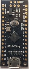
SDHC CARD 20 TRACKS RECORDER PLAYER ATtiny84
The firmware works for SDHC cards only, 4-32 GB. ATtiny84 was tested, ATtiny44 can be used but I didn't test it. The audio input is sampled at 22K per second while recording. The speed of replay can be changed in the code. ADC is set to max speed of 250KHz, TIMER0 is set as PWM is used as a DAC to convert the digital data to audio. The sound is tape quality. 180MB are allocated to each track, up to 150 minutes recording time on each track. The end address of each recorded track is written to the first sector of the track and used in playback to stop at the end of the track. Playing and Recording always starts at the start of the track.
The ADC digitizes the sound and writes it to the the SD card as raw data, no filing system is used. Every track starts at a fixed address: track number * 350,000, the end of the track address is written to the first sector of the track at the end of each recording.
SD card interfaces in SPI mode. Reading the data is in multi-blocks. OLED display is interfaced by software I2C. OLED is 128x32, 0.91", SSD1306 driver.
Holding Stop pushbutton down and pressing Play advances the track counter.
For speaker amplifier and microphone see below.
ATtiny can be programmed using Arduino IDE and Arduino as ISP, see Technical Tips Burning bootloader with setting "Clock Source 8MHz internal" and Pin Mapping: "Clockwise". When using Arduino as ISP unplug the SD card before loading the sketch to avoid 5V signals to the SD card.
SD card can tolerate 3.7V max, circuit can be powered by 3.3V including 3.7V from lithium cell, the micro SD card can be connected to a soldered SD card converter. If you need to power the circuit from 5V supply the 'microSD card adapter' is needed to supply the SD card with 3.3V power and logic, see Technical Tips.

SDHC CARD 20 TRACKS RECORDER PLAYER NANO ATtiny88
Low cost Arduino NANO with ATtiny88. The firmware works for SDHC cards only, 4-32 GB. The audio input is sampled at 22K per second while recording. The speed of replay can be changed in the code. ADC is set to max speed of 250KHz, TIMER1 is set as PWM is used as a DAC to convert the digital data to audio. The sound is tape quality.
180MB are allocated to each track, up to 150 minutes recording time on each track. The end address of each recorded track is written to the first sector of the track and used in playback to stop at the end of the track. Playing and Recording always starts at the start of the track.
The ADC digitizes the sound and writes it to the the SD card as raw data, no filing system is used. Every track starts at a fixed address: track number * 350,000, the end of the track address is written to the first sector of the track at the end of each recording.
SD card interfaces in SPI mode. Reading the data is in multi-blocks. OLED display is interfaced by software I2C. OLED is 128x32, 0.91", SSD1306 driver.
Holding Stop pushbutton down and pressing Play advances the track counter.
For speaker amplifier and microphone see below.
ATttiny is programmed using Arduino IDE. Use these instructions https://handsontec.com/
SD/SDHC CARD RECORDER PLAYER ATtiny88
Low cost Arduino NANO with ATtiny88. The firmware works for SD or SDHC cards only, 1-32 GB. The code detects whether the card is SD or SDHC and selects the proper addressing system for the card. The input is sampled at 22K per second while recording. The speed of replay can be changed in the code.
ADC is set to max speed of 250KHz, TIMER1 is set as PWM and used as a DAC to convert the digital data to audio. The sound is tape quality.
SD card interfaces in SPI mode. Reading the data is in multi-blocks.
For speaker amplifier and microphone see below.
ATttiny is programmed using Arduino IDE. Use these instructions https://handsontec.com/

SD/SDHC CARD FAT32 PLAYER ATtiny88
Low cost Arduino NANO with ATtiny88. The firmware works for SD or SDHC cards only, 1-32 GB. The code detects whether the card is SD or SDHC and selects the proper addressing system for the card. The speed of replay can be changed in the code. The sound is tape quality. TIMER1 is set as PWM is used as a DAC to convert the digital data to audio. Plays wav files PCM 22.050KHz 8 bit mono.
SD card interfaces in SPI mode. Reading the data is in multi-blocks.
For speaker amplifier see below.
ATttiny is programmed using Arduino IDE. Use these instructions https://handsontec.com/
TO SET UP THE CARD:
Format the card with FAT32.
Create sound files type .wav
Name the files with short names, 5 low case characters max + wav, ie "12.wav".
Save the files as 22.050KHz, 8 bits, mono.
Add the files to the root directory
of the card (don't use a subdirectory).

SD/SDHC CARD RECORDER PLAYER ATtiny84
The firmware works for SD or SDHC cards only, 1-32 GB. The code detects whether the card is SD or SDHC and selects the proper addressing system for the card. ATtiny84 can be used, ATtiny44 can be used but I didn't test it. The input is sampled at 22K per second while recording. The speed of replay can be changed in the code.
ADC is set to max speed of 250KHz, TIMER0 is set as PWM is used as a DAC to convert the digital data to audio. The sound is tape quality.
SD card interfaces in SPI mode. Reading the data is in multi-blocks.
For speaker amplifier and microphone see below.
ATtiny can be programmed using Arduino IDE and Arduino as ISP, see Technical Tips Burning bootloader with setting "Clock Source 8MHz internal" and Pin Mapping: "Clockwise". When using Arduino as ISP unplug the SD card while loading the sketch to avoid 5V signals to the SD card.
SD card can tolerate 3.7V max, circuit can be powered by 3.3V including 3.7V from lithium cell, the micro SD card can be connected to a soldered SD card converter. If you need to power the circuit from 5V supply the 'microSD card adapter' is needed to supply the SD card with 3.3V power and logic, see Technical Tips.

SD/SDHC CARD FAT32 WAVE PLAYER ATtiny84
The firmware works for SD or SDHC cards only, 1-32 GB. The code detects whether the card is SD or SDHC and selects the proper addressing system for the card. ATtiny84 can be used, ATtiny44 can be used but I didn't test it. The speed of replay can be changed in the code. TIMER0 is set as PWM is used as a DAC to convert the digital data to audio. The sound is tape quality. SD card interfaces in SPI mode. Reading the data is in multi-blocks.
For speaker amplifier see below.
ATtiny can be programmed using Arduino IDE and Arduino as ISP, see Technical Tips Burning bootloader with setting "Clock Source 8MHz internal" and Pin Mapping: "Clockwise". When using Arduino as ISP unplug the SD card while loading the sketch to avoid 5V signals to the SD card.
SD card can tolerate 3.7V max, circuit can be powered by 3.3V including 3.7V from lithium cell, the micro SD card can be connected to a soldered SD card converter. If you need to power the circuit from 5V supply the 'microSD card adapter' is needed to supply the SD card with 3.3V power and logic, see Technical Tips.
TO SET UP THE CARD:
Format the card with FAT32.
Create sound files type .wav
Name the files with short names, 5 low case characters max + wav, ie "12.wav".
Save the files as 22.050KHz, 8 bits, mono.
Add the files to the root directory
of the card (don't use a subdirectory).

SD/SDHC CARD WAVE PLAYER ATtiny85/45
The firmware works for SD or SDHC cards only, 1-32 GB. The code detects whether the card is SD or SDHC and selects the proper addressing system for the card. ATtiny85 or ATtiny45 can be used.
The FAT32 code is minimal, it only fined the files location and repeats playing all the songs in the order they are in the file allocation table. File names have to be short, 5 characters max, and located in the root folder.
TIMER1 set as PWM is used as a DAC to convert the digital data to audio. The sound is tape quality. The STOP pushbutton resets the ATtiny.
SD card interfaces in SPI mode. Reading the data is in multi-blocks.
For speaker amplifier see below.
ATtiny can be programmed using Arduino IDE and Arduino as ISP, see Technical Tips Burning bootloader with setting "Clock Source 16MHz (PLL)", this makes the CPU working at frequency of 16MHz. When using Arduino as ISP on 3.3V circuit unplug the SD card while loading the sketch to avoid 5V signals to the SD card.
SD card can tolerate 3.7V max, circuit can be powered by 3.3V including 3.7V from lithium cell, the micro SD card can be connected to a soldered SD card converter. When the supply is 5V the 'microSD card adapter' is needed to supply the card with 3.3V power and logic, see Technical Tips.
TO SET UP THE CARD:
Format the card with FAT32.
Create sound files type .wav
Name the files with short names, 5 low case characters max + wav, ie "12.wav".
Save the files as 22.050KHz, 8 bits, mono.
Add the files to the root directory
of the card (don't use a subdirectory).
 
FLASH MEMORY W25Q64 SOUND RECORDER AND PLAYER FOR PIC16F1827 / PIC12F1822
The ADC digitizes the sound and store it in the flash memory. 64 Mbit is enough for about 800 seconds recording. CCP1 in PWM mode is used to convert the digital data back to audio. The sound is recorder at sampling of 10KHz in a format similar to .wav files. WAV file is 54 bytes of heading followed by succession of bytes of amplitude sampling of the sound. The quality of the recorded audio is low because the PIC ADC is pushed beyond its limites, good for speech or greeting cards. W25Q interfaces the PIC in SPI mode. Reading and writing data is in entire chip mode.
When pressing RECORD erasing the chip is done first and after about 10 seconds recLED is ON to signal the start of the recording.
Audio input is 1Vp-p , you can use the mic circuit below or other source. For speaker amplifier see below.
Player: Plays flash memory w25q64 that was programmed by CH341 programmer project below or by any other SPI programmer. The player produces reasonable quality sound.
   
FLASH MEMORY W25Q64 SOUND RECORDER AND PLAYER FOR ARDUINO
The ADC digitizes the sound and store it in the flash memory. 64 Mbit is enough for about800 seconds recording. Timer2 in PWM mode is used to convert the digital data back to audio. The sound is recorder at sampling of 10KHz in a format similar to .wav files. WAV file is 54 bytes of heading followed by succession of bytes of amplitude sampling of the sound. The quality of the audio is low, good for speech or greeting cards. W25Q interfaces the Arduino in SPI mode. Reading and writing data is in all chip mode.
Recording a track requires erasing the old recording, erasing the chip takes about 10 seconds recording starts when REC LED turns on.
Audio input is 1Vp-p , you can use the mic circuit or other source. For speaker amplifier see below.
Player: Plays flash memory w25q64 that was programmed by CH341 programmer project below or by any other SPI programmer. The player produces reasonable quality sound.
 
FLASH MEMORY W25Q64 CH341 PROGRAMMER
Programmer to upload WAV file on w25q64 flash memory. WAV files up to 8MB can be uploaded and played by Arduino or PIC16F1827 above projects. Writing the memory follows erasing the chip that takes up to 30 seconds. The app is in Visual Basic VS2010.
Sound files have to be converted to wav type files PCM 11,025 KHz 8 bit Mono, max size 8MB.
In the app click Connect, find the file to upload and click Erase and Write, wait until indicated that writing is complete (up to 30 seconds).
This project is not suitable for programming BIOS memory chip.
  
SD/SDHC CARD SOUND RECORDER PIC16F1827
The ADC digitizes the sound and store it in the SD or SDHC card. The firmware works for SD or SDHC cards only. The code detects whether the card is SD or SDHC and selects the proper addressing system for the card.
The PIC's CCP is used as a DAC to convert the digital data back to audio. The sound is recorder at 20KHz 8 bits mono in a format similar to .wav files. WAV file is 54 bytes of heading followed by succession of bytes of amplitude sampling of the sound. The sound is tape quality.
SD card interfaces the PIC in SPI mode. Reading and writing data is in multi-blocks. Memory is used at the rate of 20KB/s. The Error LED indicates error sent by the SD card. The software doesn't use any file system, it just uses absolute memory addresses (raw).
Audio input is 1Vp-p , you can use the mic circuit or other source. The CCP in PWM mode gives 20KHz wave with duty cycle modulated to the audio amplitude. A low pass filter removes the 20KHz component. I added a simple 2 transistors amplifier to boost the power to drive 32 Ohm speaker or headphones. For speaker amplifier see below.
Code C for MPLABX with XC8. HEX files included.

SD/SDHC CARD WAVE PLAYER PIC16F1827 / PIC12F1822
The ADC digitizes the sound and store it in the SD or SDHC card (2-32GB). The firmware works for SD or SDHC cards only. The code detects whether the card is SD or SDHC and selects the proper addressing system for the card. Code C for MPLABX with XC8. HEX files included.
The FAT32 code is minimal, it only fineds the files location and repeats playing them. File names have to be short and located in the root folder.
The PIC's CCP is used as a DAC to convert the digital data back to audio. The sound is tape quality.
SD card interfaces the PIC in SPI mode. Reading the data is in multi-blocks. The Error LED indicates error sent by the SD card. For speaker amplifier see below.
PIC12F1822 PLAY button advances to the next track when pressed.
TO SET UP THE CARD:
Format the card with FAT32.
Create sound files type .wav
Name the files with short names, 8 low case characters max.
Save the files as 22.050KHz, 8 bits, mono.
Add the files to the root directory
of the card (don't use a subdirectory).
 
SD/SDHC CARD SOUND RECORDER
The PIC16F876A's ADC digitizes the sound and store it in the SD or SDHC card. The firmware works for SD or SDHC cards only, for old SD (before 2009) use ver1 firmware. Do not use SDXC cards with this project because some of them work on 1.8V drive. The code detects whether the card is SD or SDHC and selects the proper addressing system for the card.
The PIC's CCP is used as a DAC to convert the digital data back to audio. The sound is converted to 20KHz 8 bits mono in a format similar to .wav files. WAV file is 54 bytes of heading followed by succession of bytes of amplitude sampling of the sound. The sound is tape quality.
SD card interface the PIC in SPI mode. Reading and writing data is in multi-blocks. Memory is used at the rate of 20KB/s. The Error LED indicates error sent by the SD card. The software doesn't use any file system, it just uses absolute memory addresses (raw). Since the programme is less than 680 bytes there is much resources left for adding features.
Audio input is 1Vp-p , you can use the mic circuit or other source. The CCP in PWM mode gives 20KHz wave with duty cycle modulated to the audio amplitude. A low pass filter removes the 20KHz component. I added a simple 2 transistors amplifier to boost the power to drive 32 Ohm speaker or headphones. For speaker amplifier see below.
Code C file can be compiled with MPLAB with Hi Tech free compiler or MPLABX with XC8. HEX files included. Detailed circuit is included.
After programming the PIC16F876A connect pin 1 (reset) to 5V via 2K.

SD CARD FAT32 WAV PLAYER
PIC16F876A
This project is a .wav file type player (no recording). The software has the functions needed to read SD/SDHC card (2-32GB) formatted in FAT32. The software can play only PCM 22.050KHz, 8 bits, mono. The bytes from the file are streamed to CCP1 (PWM mode) and with an external low pass filter you get the audio. The sound is tape quality.
The software searches for files entries in the root directory only, it streams any file type without reading its name or type.
Code C file can be compiled with MPLAB with Hi Tech free compiler or MPLABX with XC8. HEX files included. Detailed circuit is included.
For speaker amplifier see below.
After programming the PIC16F876A connect pin 1 (reset) to 5V.
TO SET UP THE CARD:
Format the card with FAT32.
Create sound files type .wav
Name the files with short names, 8 low case characters max.
Save the files as 22.050KHz, 8 bits, mono.
Add the files to the root directory
of the card (don't use a subdirectory).

Circuit Description
See also Technical Tips
PIC supply is 5V. The SD Card supply, 3.3V (3-3.6V) generated
on the adapter card.
Audio input at pin 2 is 1Vp-p max. Voltage over 2Vp-p can damage the PIC input protection. 100K and 12K resistors give 0.6V DC input which is the middle of 1.25V range of the ADC.
One option is to boost the pic output by the Simple Headphones Amp. You can use a 32 Ohm speaker. For use with another amplifier connect via the lowpass filter.
Pin 1 is the PIC's reset.
22pF capacitors may need to be changed depending on the type of crystal used.
SD output at pin 7 is 3.3V but is enough to drive the PIC's input.
Stop, Rec, Pause and Play are pushbuttons.
I bought the MicroSD Adapter
on ebay; http://www.ebay.co.uk/ SD/SDHC CARD SOUND RECORDER 3.3V PIC16F690
This sound recorder has the same characteristics as the sound recorder with PIC16F876A. The difference is the supply voltage is 3.3V. This makes the direct drive of the SD card simpler. It also makes it easier to power it from a battery.
8MHz internal oscillator is used, if the frequency drifts it causes the playback to change speed. I left pins 2 and 3 free in case I have to use crystal oscillator.
The programming of the pic can be with 3.3V, if you have a pic programmer for 5V only remove the SD card while 5V is connected to the circuit, 5V will damage the SD card.Code C file can be compiled with MPLAB with Hi Tech free compiler or MPLABX with XC8. HEX files included. Detailed circuit is included.
For speaker amplifier see below.
To power the circuit from 3.7V battery see Technical Tips. SD card works on 3.6V max, for 5V supply the Micro SD Card Adapter must be used.
SD CARD FAT32 WAVE PLAYER 3.3V PIC16F690
This project is a .wav file type player (no recording). The software has the functions needed to read SD/SDHC card (2-32GB) formatted in FAT32. The software can play only PCM 22.050KHz, 8 bits, mono. The bytes from the file are streamed to CCP1 (PWM mode) . The sound is tape quality.
The software searches for files entries in the root directory only, it streams any file type without reading its name or type.
The programming of the pic can be with 3.3V, if you have a pic programmer for 5V only remove the SD card while 5V is connected to the circuit, 5V will damage the SD card.
Code C file can be compiled with MPLAB with Hi Tech free compiler or MPLABX with XC8. HEX files included. Detailed circuit is included. For speaker amplifier see below.
TO SET UP THE CARD:
Format the card with FAT32.
Create sound files type .wav
Name the files with short names, 8 low case characters max.
Save the files as 22.050KHz, 8 bits, mono.
Add the files to the root directory
of the card (don't use a subdirectory).
Troubleshooting:
If the Error LED is on immediately on power up it means that the card failed to initialize. This code works for SD card rev 2 or SDHC card, it doesn't work for SDXC (1.8V) or MMC or SD rev 1 cards. If your card is SD rev 1 you can use my firmware ver 1.
For a successful recording a sector (512 Bytes) has to be writen in 20ms, some old SD cards may be too slow writing data to the flash memory, in such case the error LED comes on. Try another make of card.
To power the circuit from 3.7V battery see Technical Tips. SD card works on 3.6V max, for 5V supply the Micro SD Card Adapter must be used.
More about FAT32 in this document: https://staff.washington.edu/
More about WAV in here: https://ccrma.stanford.edu/
Good free specifications for SD can be found in SanDisk PDF: http://alumni.cs.ucr.edu/
PIC C source code. You are free to use the circuit diagram and software with no
limitations.

Circuit Description
See also Technical Tips
PIC supply is 3.3V. The SD Card supply must be 3-3.6V.
Audio input at pin 8 is 0.8Vp-p max. Voltage over 3.3Vp-p can damage the PIC input protection. 22K,47K and 10K bias input to 0.413V DC input which is the middle range of the ADC to give 8 bits.
One option is to boost the pic output by the Simple Headphones Amp. You can use a 32 Ohm speaker. For use with another amplifier connect via the lowpass filter.
Stop, Rec, Pause and Play are pushbuttons. SD/SDHC CARD FAT32 PLAYER FOR ARDUINO
A project for Arduino Uno
or Nano with ATMEGA328P device.
The firmware works for SD or SDHC cards (2-32GB). The quality of the audio is reasonable. Plays wave files 22.050KHz, 8 bits, mono.
Timer2 in Fast PWM mode is used as a DAC to convert the digital data to audio. The PWM gives 64KHz wave with duty cycle modulated to the audio amplitude. I added a simple 2 transistors amplifier to boost the power to drive 32 Ohm speaker or headphones. For speaker amplifier see below.
SD card interfaces the microcontroller in SPI mode. Reading data is in multi-blocks. Memory is used at the rate of 20KB/s. The Error LED indicates error of communication with the SD card.
TO SET UP THE CARD:
Format the card with FAT32.
Create sound files type .wav
Name the files with short names, 8 low case characters max.
Save the files as 22.050KHz, 8 bits, mono.
Add the files to the root directory
of the card (don't use a subdirectory).

SD/SDHC CARD SOUND RECORDER FOR ARDUINO
A sound recorder project for Arduino Uno
or Nano with ATMEGA328P device.
The firmware works for SD or SDHC cards only. The quality of the audio is reasonable.
The ADC sample the input at 10K s/sec, 8 bits mono in a format similar to .wav files. WAV file is 54 bytes of heading followed by succession of bytes of amplitude sampling of the sound. Timer0 in Fast PWM mode is used as a DAC to convert the digital data back to audio. During recording the ADC converts the audio to 10 bits, the low byte is streamed to the SD card. The 0.65V bias to the ADC input is for setting the signal to the low byte of the converter output.
Audio input is 1Vp-p , you can use the mic circuit or another source. The PWM gives 64KHz wave with duty cycle modulated to the audio amplitude. I added a simple 2 transistors amplifier to boost the power to drive 32 Ohm speaker or headphones. For speaker amplifier see below.
The software includes 2 versions. sd_wave.ino uses Arduino functions only to read the SD card.
sd_sound.ino:
At the end of recording the end of track location is written to EEPROM so it is remembered at power off. Pressing Play continuously repeats the track.
SD card interfaces the microcontroller in SPI mode. Reading and writing data is in multi-blocks. Memory is used at the rate of 20KB/s. The Error LED indicates error of communication with the SD card. The software doesn't use any file system, it uses absolute memory addresses (raw).
sd_wave.ino:
Card has to be FAT32 formatted. Low quality
sound due to the file system. The code detects the type of card.
You are free to use the circuit diagram and software with no
limitations.

Circuit Description
See also Technical Tips
The 5V is generated by the arduino board.
22K 47K and 10K give the audio input 0.62V DC bias to set the ADC to the low 8 bits.
MISO card output is only 3.3V but it is ok for the 5V input of the AMD.
Audio output can use output filters as the drawing above. For microphone you can use the simple amp above.
I bought the MicroSD Adapter on ebay;
http://www.ebay.co.uk
Microphone with amplifier: eBay
Audio amplifier: eBay
 
|