|
See also PC Counter c1mhz.php
USB
FREQUENCY COUNTER AND VOLTMETER
Using PIC18F2550 for connecting analogue
and digital signals to USB port . Included Visual Basic 6 code, Visual Studio 2005 C# code, Visual Studio 2010 VB code, PIC C code for MPLABX with XC8, PIC ASM code and PIC C code for C18. Any app code works with every PIC code. The PIC microcontroller
has 10 bit analogue to digital converter, by selecting 8 bits conversion the 2 LSB are ignored. The circuit is powered
by the USB. The interface to the PC is HID class.
The frequency counter has a range of up to 12MHz (24bits). Inputs samplings can be done at rates of 1 per second and 1 every 0.1 second.
HID class (human interface device) is a class of
devices like the mouse and the keyboard, the data transfer rate
is limited to 64KB/S. The PC already has a driver for HID USB.
MPLABX, VB, and C# code is modified Microchip code from the USB framework, Microchip Solutions v2017-03-06.
VB6 code includes guidance to setting up the PC.
The PC register the PID and VID (product ID) of the USB device when
it's plugged, the VB code uses these ID's to communicate with the
device. For commercial VID it is needed to buy it from USB-IF, but in your lab you can use any number.
The VB6 and C18 source code is derived from freeware from these sources: http://janaxelson.com , http://openprog.altervista
You are free to use the circuit diagram and the VB software with no
limitations.
 
Circuit Description
See also Technical Tips
Analogue input, voltage range 0 to 5V. Max input voltage
is 5.5V .
The counter input, TTL voltage levels.
3.3V internal supply for the USB transceiver. 0.22uF is
required for regulation.
D+ D- are the data lines to the USB connector on the PC.
For USB wiring info: http://www.interfacebus.com
USB
FREQUENCY COUNTER AND VOLTMETER
Using PIC16F1459 for connecting analogue
and digital signals to USB port . Included Visual Basic 6 code, PIC C code for MPLAB-X and a circuit diagram. The PIC microcontroller
has 10 bit analogue to digital converter, by selecting 8 bits conversion the 2 LSB are ignored. The circuit is powered
by the USB. The interface to the PC is HID class.
The frequency counter has a range of up to 4MHz (24bits). Inputs samplings can be done at rates of 1 per second and 1 every 0.1 second.
HID class (human interface device) is a class of
devices like the mouse and the keyboard, the data transfer rate
is limited to 64KB/S. The PC already has a driver for HID USB.
VB6 code includes guidance to setting up the PC.
The PC register the PID and VID (product ID) of the USB device when
it's plugged, the VB code uses these ID's to communicate with the
device. For commercial VID it is needed to buy it from USB-IF, but in your lab you can use any number.
The source code is derived from freeware from these sources: http://janaxelson.com , http://openprog.altervista.org/
You are free to use the circuit diagram and the VB software with no
limitations.

Circuit Description
See also Technical Tips
Analogue input, voltage range 0 to 5V. Max input voltage
is 5.5V .
The counter input, TTL voltage levels.
3.3V internal supply for the USB transceiver. 0.22uF is
required for regulation.
D+ D- are the data lines to the USB connector on the PC.
For USB wiring info: http://www.interfacebus.com/
USB FREQUENCY COUNTER AND VOLTMETER FOR
ANDROID
Using PIC18F2550 for connecting analogue
and digital signals to Android USB port . The Android USB port is
easily accessed by imitating keyboard.
PIC C code is Microchip sample
code for USB Keyboard. The file Keyboard.c has the added code for the ADC
and the frequency counter from line 900. The USB sends 1 bytes at a
time for each key, the 11 digits of the counter and voltage are sent in 30
bytes. The HEX file is included, the c code can be compiled using C18
v3.43 with MPLAB.
The Android app is in BASIC! graphic text. http://mougino.free.fr . The app uses
graphic screen to displays voltage and frequency. The .apk file is the
file that installs manually the app to your phone. For editing the app the .bas file can be
imported after you install the RFO BASIC app to your PC and or your Android device.
HID class (human interface device) is a class of
devices like the mouse and the keyboard, the data transfer rate
is limited to 64KB/S. The PC already has a driver for HID USB.

The Android App
USB VOLTAGE,
FREQUENCY INDUCTANCE AND CAPACITANCE METER
Using PIC18F2550 for connecting analogue
and digital signals to USB port . Included Visual Basic 6 software, PIC C code and a circuit diagram. The PIC microcontroller
has 10 bit analogue to digital converter, by selecting 8 bits conversion the 2 LSB are ignored. The circuit is powered
by the USB. The interface to the PC is HID class.
The frequency meter has a range of up to 4MHz (24bits). The meter accuracy is 0.2% or better.
Inputs samplings can be done at rates of 1 per second and 1 every 0.2 second.
The cap meter
(max 50uF) measures the period of charging the cap to the Vref. The accuracy is about 5%, it depends on the charge resistors, can be calibrated by trimming 1K5 and 1M5 resistors or by the VB code.
The inductance meter (max 1H) measures the oscillation frequency of the coil under test in parallel to 0.22uF. The oscillation is triggered by a 10uS pulse from RB3. The accuracy of the measurement is about 5% and can be calibrated by the VB code or by trimming 0.22uF cap.
HID class (human interface device) is a class of
devices like the mouse and the keyboard, the data transfer rate
is limited to 64KB/S. The PC already has a driver for HID USB.
VB6 code includes guidance to setting up the PC.
The PC register the PID and VID (product ID) of the USB device when
it's plugged, the VB code uses these ID's to communicate with the
device. For commercial VID it is needed to buy it from USB-IF, but in your lab you can use any number.
The source code is derived from freeware from these sources: http://janaxelson.com/ , http://openprog.altervista.org/
Code was written on MPLAB 8x and compiled with C18 ver 3.43. PIC18F2550 was programmed using Velleman K8076.
Software includes PIC code and VB6 code. You are free to use the circuit diagram and the VB software with no
limitations.
 
Circuit Description
See also Technical Tips
PIC18F2550
Pin 3 is the analogue input, voltage range 0 to 5V. Max input voltage
is 5.5V .
Pin 11 is the counter input, TTL voltage levels.
Cx is the cap under test. BC546 selected as low leakage device for reducing error. Resistors 1M5 and 1K5 selected to give accuracy of 10%, 1K5 can be trimmed for better accuracy of uF range and 1M5 for nF range.
Lx is the coil under test. 220R triggers the coil to oscillate with parallel 0.22uF. For better stability 0.22uF should be polypropylene cap. 470K and 1K resistors on pin 4 bias the comparator input by 10mV to insure high output at idle state.
Pin 14 is 3.3V internal supply for the USB transceiver. 0.22uF is
required for regulation.
Pins 15,16 are the data lines to the USB connector on the PC.
Pin 20 is the PC 5V powering the PIC. It is limited to 100mA by
the PC. 10uF is for decoupling.
For USB wiring info: http://www.interfacebus.com/
USB OSCILLOSCOPE PIC18F2550
USB low frequency oscilloscope, bandwidth is DC to 1KHz. Max sampling rate is 12680 samples per second. The trigger circuit uses the integrated comparator and CCP. An oscilloscope with these specifications has limited use, but it has an advantage on analogue oscilloscope for low frequencies.
App 1 is
Visual Basic 6 and MPLAB C18 v3.30 or ASM, app 2 is VB2010 and MPLABX XC8. The circuit is powered by the USB. The interface
to the PC is HID class.
The screen is constructed from 64 sampling. The ADC reads the input at resolution of 8 bits and in intervals determent by the Time Base. The 64 bytes are transmitted in one stream every 100ms or longer for lower frequencies.
The trigger input starts the sampling of the input at the trigger voltage
rise. This gives the ability to measure phase shift between the trigger
and the input. The trigger input isn't needed when looking at waveform
only.
HID class (human interface
device) is a USB class of devices like the mouse and the keyboard, the
data transfer rate is limited to 64KB/S.
PIC18F2550 code is
assembly code and C code (under GNU General Public License) for Microchip C18 compiler. MPLABX code is based on Microchip MLA USB Framework.
VB6 code includes guidance to setting up the PC.
The PC register the PID (Product ID) and VID (Vendor ID) of the USB device when
it's plugged, the VB code uses these ID's to communicate with the
device. For commercial VID it is needed to buy it from USB-IF, but in your lab you can use any number.
The source code is derived from freeware from these sources: http://janaxelson.com , http://openprog.altervista.org/
Circuit Description
See also Technical Tips
PIC18F2550
Pin 3 is the analogue input. Input voltage range is 0 to 5V absolute max, voltage outside this range can latch the input or even permanently damage the IC.
Pin 4 is the comparator input used to generate the trigger.
Pin 14 is 3.3V internal supply for the USB transceiver.
Pins 15,16 are the data lines to the USB connector on the PC.
Pin 20 is the PC 5V powering the PIC. It is limited to 100mA by
the PC. 0.47uF is for decoupling.
For USB wiring info: http://www.interfacebus.com
USB
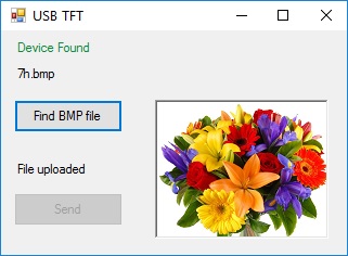
HID BMP DISPLAYED ON TFT
Using PIC18F2550 and 1.8", 160x128, ST7735 driver TFT module. Included Visual Basic 2010 code and MPLAB X XC8 code based on Microchip code. The circuit is powered
by the USB. The interface to the PC is HID class. The app in VS2010-Express works for BMP files 24 bits only. Files have to be sized to 160 px wide and 128 px high.
When USB is plugged it verifies the connection with the host and then initialize the TFT. On uploading a BMP file it displays in about 2 seconds..
HID class (human interface device) is a class of
devices like the mouse and the keyboard, the data transfer rate
is limited to 64KB/S. The PC already has a driver for HID USB.
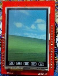
WinUSB - TFT BMP Bitmap DISPLAY See also usb_lcd for CH341 TFT.
Using PIC18F2550 for connecting LCD TFT module to USB port .
WinUSB Driver and VS2005 software
Included PIC software based on LVR software for winUSB generic driver. The PC software using Visual Basic 2005 is based on LVR version. This driver allows data transfer at a speed of 120KB/s and the screen is loaded in 2 seconds.
After connecting the programmed PIC to the PC you need to install the driver, use the INF file that included. For the missing files you can download Microchip USB framework, all the needed files are there, http://ww1.microchip.com/
VB6 and HID class USB software
Also included Visual Basic 6 code and PIC C code that interfaces the PC in HID class. HID class (human interface device) is a class of
devices like the mouse and the keyboard, the data transfer rate
is limited to 64KB/S. The PC already has a driver for HID USB.The screen loads in about 1 minute.
VB6 code includes guidance to setting up the PC.
The PC register the PID and VID (product ID) of the USB device when
it's plugged, the VB code uses these ID's to communicate with the
device. For commercial VID it is needed to buy it from USB-IF, but in your lab you can use any number.
LCD TFT Module used is 8 bits drive. Inputs to the TFT driver are level shifted from 5V to 3.3V by buffers. The LCD driver is ILI9341.
The pic firmware can read only bitmap file of 24 bits bmp type. The file has to be size of 240 pixels width and 320 pixels high. The firmware removes the bitmap header (54 bytes) and then streams the rest of the file to the TFT. Every 3 bytes are the 24 bits color for one pixel. The bitmap format reads and displays the pixels of the image starting from bottom left.
To create a *.bmp file shrink the picture to 240 pixel wide and 320 pixel high, save it as 24 bit bitmap. You can use MS Paint.
The source code is derived from freeware from these sources: http://janaxelson.com http://openprog.altervista
Code was compiled with C18 ver 3.30. PIC18F2550 was programmed using Velleman K8076 or PICKIT2.
Software includes PIC code and VB code.
Circuit Description
See also Technical Tips
RD input is connected to 3.3V on the TFT module.
RST is the RESET of the TFT Module.
The module supply is 5V. The LCD driver I have is ILI9341.
PIC18F2550
Pin 14 is 3.3V internal supply for the USB transceiver. 0.22uF is
required for regulation.
Pins 21 to 28 are port B outputs.
Pins 15,16 are the data lines to the USB connector on the PC.
Pin 20 is the PC 5V powering the PIC. It is limited to 100mA by
the PC. 0.47uF is for decoupling.
For USB wiring info: http://www.interfacebus.com
|