SMALL PROJECTS   Projects tipsTechnical Tips
Categories
Android Projects
Doorbell
PC Frequency Counters
Codelocks
Analogue
Egg Timers
Frequency Generators
LCD Frequency Counters
LED Frequency Counters
LED Thermometer
Data Loggers
LPT Interface
Birthday Cards
OBD2
OLED Frequency Counters
OLED Thermometers
Oscilloscope
SD Card Audio
Picture Frames
Serial Port Interface
Water Softeners
Talking Clocks
TFT Clocks
TFT Frequency Counters
TFT Egg Timers
Thermometers
USB Frequency Counters
CH341, LCD To USB
USB Thermometers
USB Inputs Outputs
WiFi Projects

USB TO SPI - CH341 TFT DISPLAY

CH341 module (from eBay) converts USB to I2C/SPI/EPP. The module links are set to 5V and i2c-spi. The TFT module is a 1.8" 128 X 160 pixel driven by SPI interface and using ST7735 driver IC.
PC app is in Visual Basic-VS2010, it uploads BMP files to the display.
BMP files: Resize image file to 160x128 pixels. Save the files as 24 bits bmp.
The VB wrapping of DLL is taken from GitHub https://github.com/ . DLL is installed to PC by setup.exe in downloaded driver CH341PAR.ZIP https://www.wch.cn/

ch oledoledvb

line

CH341 USB INPUT OUTPUT

CH341 module (from eBay) converts USB to I2C/SPI/EPP. The module links are set to 5V and i2c-spi. 4 digital outputs on pins D0-D3 and 4 digital inputs on pins D4-D7. PC app is in Visual Basic-VS2010, it display the digital inputs, green is high.
The VB wrapping of DLL is taken from GitHub https://github.com/ . DLL is installed to PC by setup.exe in downloaded driver CH341PAR.ZIP https://www.wch.cn/

ch clock

line

USB TO LCD USING CH341

CH341 module (from eBay) converts USB to I2C/SPI/EPP. The module links are set to 5V and i2c-spi. The LCD module is 16x2 44780 driver IC.
PC app is in Visual Basic-VS2010, it display the text on the LCD. The VB wrapping of DLL is taken from GitHub https://github.com/ . DLL is installed to PC by setup.exe in downloaded driver CH341PAR.ZIP https://www.wch.cn/

choled clock

line

USB TO I2C - CH341 CLOCK

CH341 module (from eBay) converts USB to I2C/SPI/EPP. The module links are set to 3.3V and i2c-spi. The OLED module is a 0.96" 128 X 64 pixel driven by I2C interface and using SSD1306 driver IC. The font used is 5x7 pixels universal font.
PC app is in Visual Basic-VS2010, it display the PC clock. The VB wrapping of DLL is taken from GitHub https://github.com/ . DLL is installed to PC by setup.exe in downloaded driver CH341PAR.ZIP https://www.wch.cn/

choled clock

line

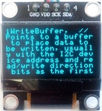
USB TO I2C - CH341 OLED TEXT

CH341 module (from eBay) converts USB to I2C/SPI/EPP. The module links are set to 3.3V and i2c-spi. The OLED module is a 0.96" 128 X 64 pixel driven by I2C interface and using SSD1306 driver IC. The font used is 5x7 pixels universal font.
PC app is in Visual Basic-VS2010, it display text written in the app to the OLED. The VB wrapping of DLL is taken from GitHub https://github.com/ . DLL is installed to PC by setup.exe in downloaded driver CH341PAR.ZIP https://www.wch.cn/

vbcholed oled

line

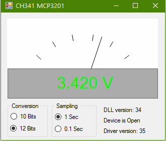
USB VOLTMETER - CH341 MCP3201

CH341 module (from eBay) converts USB to I2C/SPI/EPP. The module links are set to 5V and i2c-spi. The ADC is MCP3201 12 bit. 10 or 12 bits is selectable, reading intrvals are 1 second or 0.1 second.
PC app is in Visual Basic-VS2010, it display digital and analogue voltage. The VB wrapping of DLL is taken from GitHub https://github.com/ . DLL is installed to PC by setup.exe in downloaded driver CH341PAR.ZIP https://www.wch.cn/
LTC1285, ADS7822 are direct replacement to MCP3201.

vbcholed 

line

USB HID DRIVE OF LCD MODULE

Using PIC18F2550 for connecting 16x2 LCD module to USB port . Included Visual Basic 6 code, VS2005 C# code, vb2010 code and MPLAB X XC8 code based on Microchip code. Also C code MPLAB8.x with C18. The circuit is powered by the USB. The interface to the PC is HID class. All codes use the same PID and VID so any app works with any PIC code.
There are several makes of the LCD module that are interchangeable, the one I used is UC-16207. The LCD module has a 14 way connector, 8 pins are used for data, 2 for supply, register select(RS), read/write, enable (E) and contrast adjust. The R/W input must be connected to earth to make sure that data lines are in input mode. The VB application has only basic functions, it can be changed to interface the display for a variety of inputs.
When USB is plugged it verifies the connection with the host and then initialize the LCD. On typing a character the USB updates all the 32 characters.
HID class (human interface device) is a class of devices like the mouse and the keyboard, the data transfer rate is limited to 64KB/S. The PC already has a driver for HID USB.
VB6 code includes guidance to setting up the PC. The PC register the PID and VID (product ID) of the USB device when it's plugged, the VB code uses these ID's to communicate with the device. For commercial VID it is needed to buy it from USB-IF, but in your lab you can use any number.
The source code is derived from freeware from these sources: http://janaxelson.com/ , http://openprog.altervista.org/


Circuit Description
See also Technical Tips

PIC18F2550
Pin 14 is 3.3V internal supply for the USB transceiver. 0.22uF is required for regulation.
Pins 21 to 28 are port B outputs.
Pins 15,16 are the data lines to the USB connector on the PC.
Pin 20 is the PC 5V powering the PIC and the LCD module. It is limited to 100mA by the PC. 0.47uF is for decoupling.
For USB wiring info: http://www.interfacebus.com/

LCD Module
20K trimmer is needed to adjust the contrast voltage which vary with different batches of LCD.
Pins 7 to 14 are data inputs D0 to D7. Pin 6 is clock input, enables LCD module to read the data.
Pin 4 is Register Select input, it is used for 16 bits instruction.
Pin 5 must be connected to earth to insure that data lines are always inputs.


Name:

Comments and questions

Copy the number from the picture It stops net-robots from adding comments.


19.11.2019 - 04:44
Name: Mike C
Comment: Thanks for an very useful project!

19.11.2019 - 00:43
Name: Moty
Comment: Hi Mike, I've added a few words above that describe the use of the trigger input.

18.11.2019 - 00:47
Name: Mike C
Comment: When I need to capture a picture on scope, What do I use to trigger 18F2550 pin 4? Regards, Mike C from California, USA

11.06.2019 - 05:12
Name: Moty
Comment: Hi Lobo, The max conversion speed of the ADC is about 50 KHz even at 48 MHz clock, I take 64 sampling per frame or total of 64 KHz which is over the max.

11.06.2019 - 05:04
Name: Lobo
Comment: just build the USB-Scope on a testing board and it works well. Maybe it would be a good idea to build a protection for the input (pin 3) so there cannot be a overload. The PIC 18F2550 can be clocked with a maximum of 48MHz. Is it possible to measure a clock of more than 1KHz when the prozessor is clocked higher than the 4MHz in this circuit? If yes, can you amend the software for a 48MHz clock? Kind regards from Germany Lobo (CT8ACA)

15.08.2017 - 14:59
Name: Moty
Comment: Hallo Gunter, du bist immer willkommen

15.08.2017 - 09:22
Name: Günter
Comment: Super Seite, ich schaue immer wieder nach Neuheiten auf dieser Seite!

22.10.2015 - 12:03
Name: Mr. Valdir Bispo
Comment: Since I do not intend to work in a real Lab, I sometimes need a simple scope only to check waveforms. So I will assembly this project to hava at hand when I need, THANKS !

24.07.2015 - 10:44
Name: mysu
Comment: This project works fine for me. It can be made to work on a Android tablet? A tablet is more portable in comparison to laptop and battery last longer.

24.07.2015 - 10:44
Name: mysu
Comment: This project works fine for me. It can be made to work on a Android tablet? A tablet is more portable in comparison to laptop and battery last longer.

28.06.2015 - 16:23
Name: Moty
Comment: Hi Memo, The input voltage shouldn't be more positive than the Vdd and not lower than ground. Look at Technical Tips page how you can protect the input of the PIC.

28.06.2015 - 06:40
Name: Memo
Comment: Hi Moty...I'm going to do this project, but I ask you: What is the maximum voltage amplitude that I can measure to the input? (3V, 5V ...)

19.09.2014 - 08:41
Name: gedstron
Comment: please, can you please upgrade it to graphic lcd 128x64 oscilloscope.thanks

05.06.2014 - 23:04
Name: Moty
Comment: Hi Moondeck. When the trigger is not connected the waveform runs free. If the trigger is connected to the signal input and TRIGGER selected on the PC app it is like an auto-trigger, the waveform will be stable. Are you related to Frank Zappa? he named his daughter Moonunit.

05.06.2014 - 22:06
Name: Moondeck
Comment: Hi. Where should i wire the Trigger? Or can i just leave it N.C.d ?

20.05.2014 - 12:16
Name: mirob
Comment: Thanks! :-)

20.05.2014 - 11:59
Name: mirob
Comment: Thanks! :-)

20.05.2014 - 11:59
Name: mirob
Comment: Thanks! :-)

20.05.2014 - 10:18
Name: Moty
Comment: Hi Mirob. The cap is 0.22uF.

20.05.2014 - 08:33
Name: mirob
Comment: capacitor for pine microprocessor 14 has a value of 0.22 ..... what? uF, nF, pF ...?

23.10.2013 - 20:08
Name: Ahmed
Comment:

14.09.2013 - 22:33
Name: Moty
Comment: Hi Chandana. It is difficult to remotely find the problem. Some people needed to add USB HID driver to their WIN XP. In most cases it was a free PIC programmer that didn't work well with PIC18F2550.

14.09.2013 - 09:06
Name: chandana
Comment: I built this project, VB screen is open but the device is not recognized. I appreciate your advice. Thanks

22.08.2013 - 22:18
Name: Moty
Comment: Hi Edson. The problem is likely to be in the programming of the PIC. Are you using a programmer which you know works well for pic18f2550 ?

21.08.2013 - 23:10
Name: Edson Stedile
Comment: I built this project, however the the VB screen points out that the device is not recognized. I appreciate your advice. Thanks

27.05.2013 - 11:39
Name: Moty
Comment: Hi Momgoose. Make sure "usb_defs.inc" and "ENGR2210.inc" are included in the project. Make sure the project Set Tool Location is directed to the correct folder in your computer where you keep the inc and lib files.

26.05.2013 - 01:35
Name: Mongoose
Comment: Hi, i'm trying to compile your asm file in MPASMWIN and I have many errors. Can you help me? Thank you.

19.03.2013 - 19:53
Name: Moty
Comment: Hi, I assume that the problem is that the device isn't detected by the VB application. All USB devices communicate with the PC the same way. The PC identifies each device by 2 numbers called VID and PID. The scope and the input output projects use deferent VID and PID, it means that the scope VB application detects only the scope firmware, the same for the input output firmware. The VID and PID are programmed in the firmware and in the VB code. You can change the numbers but you have to have the same number in the firmware and in the VB code. After you programme the PIC unplug the device and plug it again, it lets the PC to check the device. If the PC doesn't recognize the device then it could be an error with writing the firmware to the PIC. I hope I've answered your question, don't hesitate to ask more. And one more thing, I adore France.

19.03.2013 - 17:22
Name:
Comment: When using USB Input-Output hex file the device is recognized by the computer, while when I write USB Oscilloscope hex file it is not. The hardware uses in both cases 4 MHz osc. Why is it rejected? Thanks in advance

06.03.2013 - 06:42
Name: DVS
Comment: It's good but please give more details about trigger pin.........

05.03.2013 - 16:43
Name: Moty
Comment: I'm glad to hear that. Have fun.

05.03.2013 - 07:33
Name: SRIDHAR DV
Comment: It's very usefull for me......

05.03.2013 - 07:33
Name: SRIDHAR DV
Comment: It's very usefull for me......

16.02.2013 - 08:50
Name: Satya Ranjan Sarkar
Comment:

02.09.2012 - 13:06
Name: ffgh
Comment:

18.06.2012 - 13:11
Name:
Comment: what is the max input power and max amplitude the adc can digitise

17.06.2012 - 10:06
Name:
Comment: can you describe the A/D conversion process in some detail, also what does the time base do in your project.

10.06.2012 - 15:03
Name: Moty
Comment: The comparator of the pic detects when the signal crosses 0V and starts the input sampling.

10.06.2012 - 08:35
Name: can you please give me more detail about the trigger.
Comment:

12.09.2010 - 06:43
Name: Faiz Alam
Comment: Very good

icon Flag Counter moty22.co.uk  2008-2025