|
For signal lower than 5V use high speed comperator: eBay
PIC12F1822 16MHz FREQUENCY COUNTER FOR CHROME BROWSER
The frequency can be displayed in Chrome, Edge and Opera browsers https://developer.chrome.com/ . Run the PIC connected via USB to Serial Adapter, open file counter.html in the browser and click Connect. The html includes javascript.
The PIC12F1822 microcontroller is programmed to count the input frequency during accurate 1 second derived from the 8 MHz crystal. The counter measures the frequency for 0.1sec first, if the frequency is greater than 2MHz TMR0 prescaler divides by 4 to increase the input frequency range to 16MHz with resolution of 4Hz, when the frequency is below 2MHz TMR0 is set for no prescaling and the measurment is with resolution of 1Hz.
The micro controller is powered
by 5V output from the USB to UART Adapter. When pluging the module it creates a serial port on the PC which can be found in Device Manager.
  
PIC12F1822 16MHz FREQUENCY COUNTER
USING USB TO UART
Self powered frequency counter
plugged into a USB port. The PIC12F1822 microcontroller is programmed to count the input frequency during accurate 1 second derived from the 8 MHz crystal. The counter measures the frequency for 0.1sec first, if the frequency is greater than 2MHz TMR0 prescaler divides by 4 to increase the input frequency range to 16MHz with resolution of 4Hz, when the frequency is below 2MHz TMR0 is set for no prescaling and the measurment is with resolution of 1Hz.
The micro controller is powered
by 5V output from the USB to UART module. When pluging the module it creates a serial port on the PC which can be found in Device Manager, set the VB app to connect to that port number. Every second the PIC sends 3 bytes of data to the PC.
The app includes an option for talking the frequency.
PC app is in Visual Studio (VS2010) code
and App (EXE) are included.
USB to UART can be bought in Ebay https://www.ebay.co.uk/ make sure it has 5V output.
  
 TALKING FREQUENCY COUNTER
USING USB TO UART
Self powered frequency counter
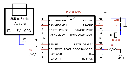
plugged into a USB port. The PIC16F628A microcontroller is programmed to count the input frequency during accurate 1 second derived from the 16 MHz crystal. The micro controller is powered
by 5V output from the USB to UART module. When pluging the module it creates a serial port on the PC which can be found in Device Manager, set the VB app to connect to that port number. Every second the PIC sends 3 bytes of data to the PC.
The app includes an option for talking the frequency.
Included a Visual Studio (VS2010) code
and App and pic C code for MPLAB X.
USB to UART can be bought in Ebay https://www.ebay.co.uk make sure it has 5V output.
  
ARDUINO FREQUENCY COUNTER FOR CHROME BROWSER
The frequency can be displayed in Chrome, Edge and Opera browsers https://developer.chrome.com . Run the Arduino connected to USB, open file counter.html in the browser and click Connect. The html includes javascript.
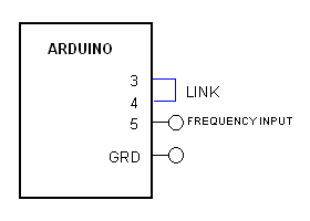
Arduino Uno or Nano generates an accurate 1 second time base for the counter by cascading timer0 and timer2. The link between digital inputs 3 and 4 connects the output of timer2, 250 Hz, to input of timer0. The software waits for the output of timer0 to go positive to start the count of frequency input to timer1. Timer1 is a 16 bits timer, it overflows at the count of 2 power of 16, that in turn advances overFlow register. At the end of the 1 second the 16 bit register is recorded. The Arduino then sends to the PC via the USB cable and the Com Port a string of the calculated frequency.
The frequency input at pin 5 is TTL signal levels. The specs recommend input up to 6 MHz.
 
6MHz ARDUINO FREQUENCY COUNTER FOR PC
Arduino Uno or Nano generates an accurate 1 second time base for the counter by cascading timer0 and timer2. The link between digital inputs 3 and 4 connects the output of timer2, 250 Hz, to input of timer0. The software waits for the output of timer0 to go positive to start the count of frequency input to timer1. Timer1 is a 16 bits timer, it overflows at the count of 2 power of 16, that in turn advances overFlow register. At the end of the 1 second the 16 bit register is recorded. The Arduino then sends to the PC via the USB cable and the Com Port 4 bytes of data.
VB6: The Arduino has to be connected to the PC first and then the VB6 app started. The app searches for the Com Port by sending a byte and checking if the byte is echoed. It takes a few seconds.
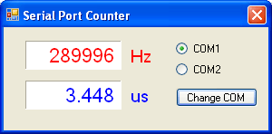
VS2010: Select COM Port that is connected to the Arduino. Included option for talking frequency.
The frequency input at pin 5 is TTL signal levels. The specs recommend input up to 6 MHz, I tested it at 2 MHz.
Included a Visual Basic (VB6) code, Visual Studio 2010 and Arduino sketch.
 
 SERIAL
PORT 1MHz / 100KHz FREQUENCY COUNTERS
1MHz:
Self powered frequency counter
plugged into the serial port. Included a Visual Basic (VB6 and VS2005) code
and .EXE file, PIC assembly, PIC C code, and a circuit diagram. The PIC16F628A microcontroller is programmed to count the input frequency and transmit
it serially to the serial port. The micro controller is powered
by the signals of the serial port, so no external power supply is
needed. The counter is 20 bit transmitted by the UART in 3 bytes. The crystal
can be changed to a ceramic resonator if accuracy isn't essential.
100KHz:
Self powered frequency counter
plugged into the serial port. Included a Visual Basic (VB6) code, PIC code, and a circuit diagram. The PIC16F628A microcontroller is programmed to count the input frequency and transmit
it serially to the serial port. The microcontroller is powered
by the signals of the serial port, so no external power supply is
needed. The counter is 17 bit (16 bits + overflow). The crystal
can be changed to a ceramic resonator if accuracy isn't essential.
The signal input is connected via the chip comparator to allow sensitivity down to 100mV.
You can read more about serial interface in http://www.beyondlogic.org
You are free to use the circuit diagram and the software with no
limitations.
Software includes PIC code and VB6 code.
You can read more about serial interface in http://www.beyondlogic.org
Code is for MPLAB, MPLABX and compilers HI TECH or XC8.
You are free to use the circuit diagram and the software with no
limitations.
 
Circuit Description
See also Technical Tips
Pin 4 at the serial port is
turned to +12V by the software enabling RTS. It is regulated to
5V by 78L05. The 5V is the supply to the microcontroller.
Pin 3 is at -12V and pin 7 at +12V
constantly and they are used to drive RX input between -9V (input
HIGH) and +8v (input LOW) . These levels are sufficient to drive
the RS242 input.
Pin 12 is the frequency input, input signal has to be TTL type.
Pin 8 is the UART output, it transmits the 20 bit count in three bytes in RS232 format. When pin 8 is high both transistors conduct and voltage at pin 2 of serial port is at -9V.
The other pins are not in use but must be left open circuit.  
Circuit Description
See also Technical Tips
Pin 4 at the serial port is
turned to +12V by the software enabling RTS. It is regulated to
5V by 78L05. The 5V is the supply to the microcontroller.
Pin 3 is at -12V and pin 7 at +12V
constantly and they are used to drive RX input between -9V (input
HIGH) and +8v (input LOW) . These levels are sufficient to drive
the RS232 input.
PIC16F628A contains a UART for serial comm and a 16
bit counter.
Input signal can be 0.1 to 5 vollts peak to peak.
Pin 17 is the frequency input, it's the PIC comparator input. Referance voltage to the comparator is 2.5V at pin 1. Output of the comparator at pin 2 is linked to the PIC counter input at pin 12.
Pin 8 is the UART output, it transmits the 16 bit count and overflow
in three 8 bit words in RS232 format.
The other pins are not in use but must be left open circuit.
| ![]()
moty22.co.uk 2008-2025