RTC DS3231 TFT CUCKOO CLOCK PIC16F690
Clock with PIC connected to RTC DS3231. The pic enquier the time every second. The DF-Player plays the cuckoo sound once every 15 minutes and on the hour it plays the number of hours.
The download includes sound file, format the SD card FAT32 and copy the sound file to the root directory.
The TFT module is 1.8 inch screen, 160x128, the driver ic ST7735, SPI interface.
   
RTC DS3231 TFT CUCKOO CLOCK ARDUINO
Clock with Arduino Uno or Nano connected to RTC DS3231. The pic enquier the time every second. The JQ6500 Player plays the cuckoo sound once every 15 minutes and on the hour it plays the number of hours.
The software includes sound file. JQ6500 includes an app that lets you upload sound files. The cuckoo sound has to be the first or the only file on the internal memory.
The TFT module is 1.8 inch screen, 160x128, the driver ic ST7735, SPI interface.
   
LED REAL TIME CLOCK ATtiny88
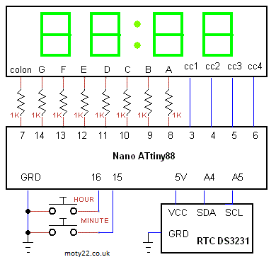
7 segments LED display, Low cost Arduino Nano with ATtiny88 Real Time Clock. Hours and minutes are set by buttons.
Included ino sketch file for common cathode LED and ino file for common anode LED. When using common cathode LED colon 1K resistor is connected to 5V. When using common anode LED colon 1K resistor is connected to GRD. cc1 is the left digit. The LED I used is 5643BS-1. Brightness is set by the value of the 1K resistors, minimum value is 680R to avoid MC output max current.
ATttiny can be programmed using Arduino IDE. Use these instructions https://handsontec.com/
   
LCD CLOCK WITH LARGE CHARACTERS
Arduino Uno or Nano with LCD 1602 clock. Large figures are made of 8 custom created characters, each number is made of 6 characters.
The clock is as accurate as the built in crystal. 1 second time base is division by timer1 and timer2. Link between pins 5 and 3 connects output of timer2 to input of timer1.
Arduino modules have either 16MHz crystal with 50 ppm tolerance or 16MHz ceramic resonator with tolerance of 0.5% and temperature stability of 0.2%. The crystal is more accurate.
Seconds are displayed in normal size number.
the pushbuttons set the hours and the minutes.
 
RTC DS3231 OLED CLOCK PIC16F1827 / PIC12F1822
OLED clock with PIC connected to RTC DS3231. The day month and year are displayed. MODE button selects what part off date to set, the part is marked with a line. Button INC changes the value. The pic enquier the date every second.
PIC12F1822 sets SQW to 1Hz it used to trigger time reading.
You are free to use the circuit diagram and the software with no limitations.
   
RTC DS3231 OLED CLOCK ATtiny45 / 85
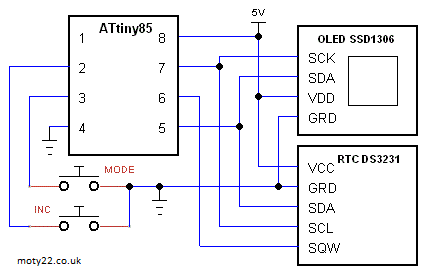
OLED clock with ATtiny85 or ATtiny45 connected to RTC DS3231. The day month and year are displayed. MODE button selects what part off date to set, the part is marked with a line. Button INC changes the value.
ATtiny sets SQW to 1Hz it used to trigger time reading.
ATtiny can be programmed using Arduino IDE and Arduino as ISP, see Technical Tips Burning bootloader with setting "Clock Source 4MHz(internal)", this makes the CPU working at frequency of 4MHz.
  
RTC DS3231 LCD CLOCK TEMPERATURE
LCD clock with PIC16F628A / PIC16F1827 connected to RTC DS3231. The day, month, year and temperature are displayed, temperature measurment is sourced by the RTC. SQW is set to 1Hz and used to trigger time reading. PIC16F628A uses software I2C toread the RTC.
MODE button selects what part off date to set, the part is marked with 2 letters ie minute=mi. Button INCREASE chnges the value. The pic enquier the date every second.
You are free to use the circuit diagram and the software with no limitations.
  
PIC12F629 CLOCK TM1637 DISPLAY
24 hour clock with watch crystal. Included C code for MPLAB X and circuit diagram.
Display is 9mm 7 segment 4 digits LED: TM1637. Brightness can be set in software level 0 to 7.
You are free to use the circuit diagram and the software with no limitations.
 
PIC12F629 CLOCK OLED DISPLAY
24 hour clock with watch crystal. Included C code for MPLAB X and circuit diagram.
OLED display, 128x64 - 0.96" or 128x32 - 0.91", SSD1306, I2C. Brightness can be set in software.
If using 128x32 OLED change code in main() oled_init(64); to oled_init(32); HEX files for both OLEDs are included.
  
TFT
CLOCK + THERMOMETER
LCD TFT is digital display at its best, it displays versatile clear picture. The picture is built by entering the address and the color of a pixel or rectangle, so it's simple to use too.
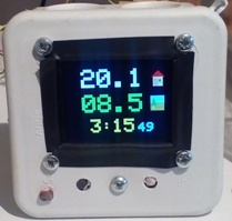
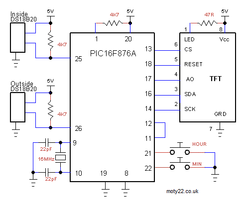
Clock based on PIC16F876A 1.8" LCD TFT Module. Included C code,
makefile for MPLAB X, hex file and circuit diagram. Fonts are 5 bytes
long each they are stored in the flash memory of the PIC.
Seconds timebase for the clock is a division of the 16MHz crystal using
CCP1, CCP2, TMR1 and TMR2. A link of pins 11 and 12 connects the output
of CCP2 to TMR1 input.
2xDS18B20 digital sensors are for measuring temperatures inside and
outside the house. The temperature range is -55 to 99.9 centigrade. The
sensor doesn't require calibration. The software updates the reading
every 30 seconds.
LCD TFT module has the driver ST7735 size is 1.8" 160x128 pixels.
https://www.ebay.co.uk/
. Inputs of the driver tolerate 5V, the board has 3.3V regulator for the
driver.
You are free to use the circuit diagram and the software with no limitations.
 
Circuit Description
See also Technical Tips
DS18B20 is a digital temperature sensor, any case type
can be used.
The crystal is 16 MHz, refer to the data sheet for the recommended capacitors. Most crystals use 22pF.
Link between pins 11 and 12 connects 5 KHz generated by CCP2 driving TMR1 and CCP1 to give timebase of 1 sec.
The TFT module in the project has the driver ic ST7735 . LED input is connected
directly to the led's,
the 47 ohm resistor is selected to give max
brightness, the resistance can be increased to reduce the light.
HOUR and MINUTE pushbuttons can be any type of NO switch. |
![]()
moty22.co.uk 2008-2025