Compiling and Programming
The PIC12 and PIC16 projects are compiled with HI-TECH C compiler or XC8. PIC18 projects are compiled with MICROCHIP C18 compiler ver. 3.30 or 3.43 or XC8. MPLAB8.x or MPLAB X are used.
Sourcing components: some components can be bought directly from China because the price is more sensible. I use eBay for most of the components. Avoid buying from http://www.banggood.com when you order small quantity they label you as not valuable customer and send you rubbish out of their bin.
Prototyping
I use breadboard to develop the circuits on, and find it easy to use stripboard to build the projects on.


Where it is possible I choose components that are widely available, where the value and type isn't very critical to the operation of the circuit. In digital circuits values aren't critical because most resistors are used for pull up or current limit.
Resistors are 0.5 - 0.25 watt, carbon film, 5% tolerance. Metal film resistors can be used too.
Polarized capacitors are electrolytic, 10V or higher. Capacitors of values between 1uF to 1nF are either plastic film or ceramic. Values in pF (used for the oscillator) are ceramic. The voltage can be 10V upwards.
Transistors are plastic package, TO92 or similar, unless otherwise stated in the project.


Sourcing components vary greatly between countries so it's hard to give good tips, Ebay can be a good source,
If you recycle components from old projects or old appliances you might be helping the environment and your pocket too.
Programming ATtiny44/84/25/45/85 using Arduino Uno or Nano
1. Add "ATtinyCore" as in these instructions: https://gist.github.com/ij96/804e731bd31dbb95b2b043e93c79ceab
2. Wire the Arduino to the ATtiny:
| Arduino |
ATtiny13/25/45/85 |
ATtiny44/84 |
|
| 5V |
8 |
1 |
VCC |
| GRD |
4 |
14 |
GRD |
| 10 |
1 - P5 |
4 - PB3 |
RESET |
| 11 |
5 - P0 |
7 - PA6 |
MOSI |
| 12 |
6 - P1 |
8 - PA5 |
MISO |
| 13 |
7 - P2 |
9 - PA4 |
SCK |
3. Add a 10uF capacitor between RESET and GND on Arduino, to avoid auto-reset while uploading program to ATtiny85.
4. Burn Bootloader.
5. Upload Sketch.
Supply decoupling capacitors
Microcontrollers require decoupling cap of 0.1 to 1 uF across the supply, if the MC is a few centimetres from the output cap of the power supply 0.1uF is enough, longer distances the decoupling cap has to be near the MC and at least 1uF.
Without decoupling cap you may get unexpected operations.
Analogue voltage input
To increase the input voltage range use a voltage divider.

R2 can be up to 10K.
R1 = (Vin - 5) * R2 / 5
CALCULATOR:
Use metal film resistors for better temperature stability. If Vin is a multiplications of 5 you can use R1 made of serially connected resistors with the same value of R2, and in this case you can use 5% carbon film resistors.
Example: for Vin = 20V, R2 = 10K and R1 = 3 resistors of 10K in series.
The measured voltage is as accurate as the 5V supply because the Vref is connected to the Vcc. If your supply voltage isn't 5V you can compensate for the error in the VB application.
1N4148 diodes (or equivalents) and 1K resistor protect the input of the IC, they are recommended option.
OUTPUT DRIVE
Three common ways of pic output drive:
driving relay,
driving power mosfet to switch high DC current,
driving opto-isolated triac to switch AC.

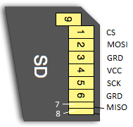
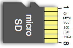
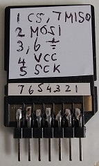
SD Card
SD card works on 3.6V max or 3.7V cell, for 5V supply or logic drive the Micro SD Card Adapter must be used. Micro SD Card can be used by soldering "Micro SD to SD adapter".


![]()
moty22.co.uk 2008-2026