|
OBD2 LIVE SENSOR SCANNER PIC16F876A
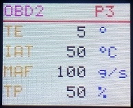
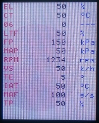
This project is suitable for cars with OBD2 CAN protocol ISO 15765 11 bits 500 Kb/s, most cars have this protocol. The application reads data of the ECU . The vertical version app all 12 common PIDs are displays on one screen in smaller text, the horisontal app displays 12 PIDs (parameters) in 3 pages. NEXT pushbutton cycles through the pages. Page 0 stops the scanning.
TFT screen is 160x128 pixels, 1.8 inch with ST7735 driver.
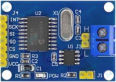
The MCP2515 module drives the CAN BUS. The circuit supply is from the car 12V , 5V regulator generates the 5V for the TFT and MCP2515. Setting up filters in the MCP2515 is for allowing only 7DF messages to be read by the PIC.
The code requests the data every second. The request is an address 7DF, number of bytes, service #, PID and padding 5 bytes of 0x55. The reply from the ECU is address 7E8, number of bytes, 0x41, PID and 2 bytes of data. The data i calculatedRPM = (byte1*256+byte2)/4.
The C code is migrated from Arduino lib, C++ was changed to C so it can be compiled by the free XC8.
After programming the PIC16F876A connect pin 1 (reset) to 5V.
Circuit Description
See also Technical Tips
MCP2515 CAN driver https://www.ebay.co.uk
OBD2 plug https://www.ebay.co.uk
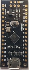
OBD2 LIVE SENSOR SCANNER ATtiny88
This project is suitable for cars with OBD2 CAN protocol ISO 15765 11 bits 500 Kb/s, most cars have this protocol. The ATtiny88 is a low cost Arduino Nano. The application reads data of the ECU . All 12 common PIDs are displays on one screen. NEXT pushbutton starts the scanning.
TFT screen is 160x128 pixels, 1.8 inch with ST7735 driver.
The MCP2515 module drives the CAN BUS. The circuit supply is from the car 12V , 5V is sourced from the ATtiny88 module. Setting up filters in the MCP2515 is for allowing only 7DF messages to be read by the PIC.
The code requests the data in sequence with timeout of 1 second, when timed out display is 0. The request is an address 7DF, number of bytes, service #, PID and padding 5 bytes of 0x55. The reply from the ECU is address 7E8, number of bytes, 0x41, PID and 2 bytes of data.
The C code is migrated from Arduino lib, code was changed to fit in the smaller memory of the ATtiny. The application reads data of the ECU .
ATttiny can be programmed using Arduino IDE. Use these instructions https://handsontec.com/
MCP2515 CAN driver https://www.ebay.co.uk
OBD2 plug https://www.ebay.co.uk
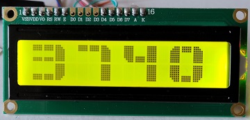
 OBD2 RPM METER PIC16F876A / PIC16F690
This project is suitable for cars with OBD2 CAN protocol ISO 15765 11 bits 500 Kb/s, most cars have this protocol. The application reads data of the ECU . The MCP2515 module drives the CAN BUS. The circuit supply is from the car 12V , 5V regulator generates the 5V for the LCD and MCP2515. Setting up filters in the MCP2515 is for allowing only 7DF messages to be read by the PIC.
The code requests the data every second. The request is an address 7DF, number of bytes, service #, PID and padding 5 bytes of 0x55. The reply from the ECU is address 7E8, number of bytes, 0x41, PID and 2 bytes of data. The data i calculatedRPM = (byte1*256+byte2)/4.
The C code is migrated from Arduino lib, C++ was changed to C so it can be compiled by the free XC8.
After programming the PIC16F876A connect pin 1 (reset) to 5V.
Circuit Description
See also Technical Tips
MCP2515 CAN driver https://www.ebay.co.uk
LCD 16 x 2 module https://www.ebay.co.uk
OBD2 plug https://www.ebay.co.uk
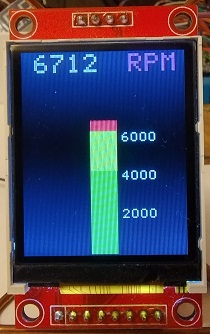
OBD2 TFT RPM METER PIC16F690
This project is suitable for cars with OBD2 CAN protocol ISO 15765 11 bits 500 Kb/s, most cars have this protocol. The application reads data of the ECU . The MCP2515 module drives the CAN BUS. The circuit supply is from the car 12V , 5V regulator generates the 5V for the TFT and MCP2515. Setting up filters in the MCP2515 is for allowing only 7DF messages to be read by the PIC.
TFT screen is 1.8" 160x128 pixels with ST7735 driver. Bar height indicates RPM.
The code requests the data every 0.1 second. The request is an address 7DF, number of bytes, service #, PID and padding 5 bytes of 0x55. The reply from the ECU is address 7E8, number of bytes, 0x41, PID and 2 bytes of data. The data i calculatedRPM = (byte1*256+byte2)/4.
The C code is migrated from Arduino lib, C++ was changed to C so it can be compiled by the free XC8.
MCP2515 CAN driver https://www.ebay.co.uk
OBD2 plug https://www.ebay.co.uk
OBD2 OLED RPM METER ATtiny88
This project is suitable for cars with OBD2 CAN protocol ISO 15765 11 bits 500 Kb/s, most cars have this protocol. The ATtiny88 is a low cost Arduino Nano. The application reads data of the ECU . The MCP2515 module drives the CAN BUS. The circuit supply is from the car 12V , 5V from the ATtiny board powers the OLED and MCP2515. Setting up filters in the MCP2515 is for allowing only 7DF messages to be read by the PIC.
OLED display is 0.96" 128x64 I2C. The OLED is driven by software I2C.
The code requests the data every 0.5 second. The request is an address 7DF, number of bytes, service #, PID and padding 5 bytes of 0x55. The reply from the ECU is address 7E8, number of bytes, 0x41, PID and 2 bytes of data. The data i calculated RPM = (byte1*256+byte2)/4.
The C code is migrated from Arduino lib, C++ was changed to C, a few changes to the code made it possible to work on the ATtiny with 8KB memory. Keep INO and C files in the same folder.
ATttiny can be programmed using Arduino IDE. Use these instructions https://handsontec.com/
MCP2515 CAN driver https://www.ebay.co.uk
OBD2 plug https://www.ebay.co.uk
PC APP FOR CAN OBD2
This project is suitable for cars with OBD2 protocol ISO 15765 11 bits 500 Kb/s, most cars have this protocol. The application reads data of the ECU using CAN. The MCP2515 module drives the CAN BUS. The circuit supply of 5V is from the USB, the Arduino is plugged to the PC USB. The app reads 17 most common PIDs. The app calculates the data from the ECU.
The PID button is for reading ECU results for MODE and PID numbers typed in the TextBox next to the button (ie 010D). Button SAVE saves text file of readings in the app folder.
For compiling the Arduino code you need to install a lib from GitHub. Lib for the Arduino can be downloaded from GitHub: https://github.com/
OBD2 plug https://www.ebay.co.uk
OBD2 LCD FOR CAN PROTOCOL
This project is suitable for cars with OBD2 protocol ISO 15765 11 bits 500 Kb/s, most cars have this protocol. The application reads data of the ECU using CAN. The MCP2515 module drives the CAN BUS. The circuit supply is from the car 12V , the Arduino generates the 5V for the LCD and MCP2515. The code reads 12 most common PIDs and calculates the data from the ECU. The code requests data when pressing button PID.
For compiling the code you need to install a lib from GitHub. Lib for the Arduino can be downloaded from GitHub: https://github.com
More
PIDs can be added to the Arduino code.
OBD2 plug https://www.ebay.co.uk
 
LCD
OBD2 REV COUNTER
This project is suitable for cars with OBD2 protocol ISO 15765 11 bits 500 Kb/s, most cars have this protocol. The application reads data of the ECU using CAN. The MCP2515 module drives the CAN BUS. The circuit supply is from the car 12V , the Arduino generates the 5V for the LCD and MCP2515.
For compiling the code you need to install a lib from GitHub. The code requests the data twice every second. The request is an address 7DF, number of bytes, service #, PID and padding 5 bytes of 0x55. The reply from the ECU is address 7E8, number of bytes, 0x41, PID and 2 bytes of data. The data i calculatedRPM = (byte1*256+byte2)/4.
Lib for the Arduino can be downloaded from GitHub: https://github.com
CAR SIMULATOR
OBD2 car simulator Using Arduino Nano and MCP2515 CAN driver. It simulate ISO
15765-4 CAN BUS 11 bit, 500 Kb/s. obd_sim.ino is for Bluetooth with ELM v2.1, obd_usb_sim.ino is for USB OBD plug with ELM v1.5.
Only most common PIDs are simulated. The
simulator listen to messages from an Diagnostic tool and reply as an ECU. It
can be used to test Diagnostic tool or to be used for development.
More
PIDs can be added to the Arduino code. The code is a revised code from
example in the GitHub MCP CAN LIB library that needs to be added to the
Arduino IDE, https://github.com/ .
The ODB socket I used is: https://www.ebay.co.uk
Circuit Description
See also Technical Tips
MCP2515 CAN driver https://www.ebay.co.uk
LCD 16 x 2 module https://www.ebay.co.uk
OBD2 plug https://www.ebay.co.uk
The ODB socket for the simulator: https://www.ebay.co.uk
OBD2 applications in this page work with most ELM327 OBD Plugs including some imitation plugs from eBay, it's done by apps reading any text message and processing the data only.
OBD2 APPLICATIONS
Android app uses OBD2 to USB, it has ELM327 that connects to all OBDII protocols. The app reads common PIDs, DTC (faults) and VID. Code is in B4A (basic for android) https://www.b4x.com/
Windows application reads current data. The bluetooth obd2 plug has ELM327 that connects to all OBDII protocols. The computer's bluetooth pairs with the OBD-II plug and connects to the app via COM Port. On windows computer you can find the COM port number in 'device manager' and select the port in the app.
In here https://en.wikipedia.org/ you can find the parameter IDs of data request. A request is 2 hexadecimal numbers and the ELM response is several bytes that contain the data. Every car responds to different request, the app has only 12 popular requests, others can be added.
The bluetooth plug used: https://www.ebay.co.uk/
The USB diagnostic plug with ELM327 v1.5, connected to Android device via OTG adaptor.
https://www.ebay.co.uk/
You are free to use the circuit diagram and the VB software with no limitations.
ANDROID APP FOR BLUETOOTH / USB OBD2
The Android app was made using MIT App Inventor which is an easy way to make
Android apps. Measure common parameters, DTC (faults) and VID (vehicle ID). The
Android device, phone or tablet, have to be paired with the BT plug.
The app APK file, has to be transferred to the device
and when opened it instructs how to be installed. .aia file is the app and
can be modified in the MIT App Inventor https://appinventor.mit.edu/.
The Bluetooth plug I used, make sure it's ELM327 V2.1: https://www.ebay.
The USB diagnostic plug with ELM327 v1.5, connected to Android device via OTG adaptor.
https://www.ebay.co.uk/

REV COUNTER ANDROID B4A
A rev counter connected
to OBD2 diagnostic plug with ELM327. This RPM meter works with all
OBD protocols. The Android program is written using B4A (basic for Android).
The
display is digital and traditional analogue. The app request data from the
car ECU every 0.2 sec. The app APK file, has to be transferred to the device
and when opened it instructs how to be installed. B4A code is included, if
you want to edit the code free IDE can be found at
https://www.b4x.com/.
The Android device, phone or tablet, has to be paired with the Bluetooth plug.
The OBD2 Bluetooth diagnostic plug with ELM327 v2.1: https://www.ebay.
The USB diagnostic plug with ELM327 v1.5, connected to Android device via OTG adaptor.
https://www.ebay.co.uk/
  
REV COUNTER ANDROID APP INVENTOR
A rev counter connected
to OBD2 Bluetooth diagnostic plug with ELM327. This RPM meter works with all
OBD protocols. The Android program is written using MIT App Inventor https://appinventor.mit.edu/. The
Android device, phone or tablet, have to be paired with the BT plug. The
display is digital and traditional analogue. The app request data from the
car ECU every 0.5 sec. The app APK file, has to be transferred to the device
and when opened it instructs how to be installed. .aia file is the app and
can be modified in the MIT App Inventor.
The Bluetooth plug I used: https://www.ebay.co.uk/
If you buy it locally, make sure it's ELM327 V2.1

|