|
SD CARD TEMPERATURE / VOLTAGE LOGGING
Logging temperature from sensor DS18B20 -55 to 125 deg C or 5VDC input to the PIC's ADC. Logs up to 65,000 readings to a TXT file on a CD Card formatted FAT32, cards can be SD or SDHC (up to 32GB). PIC16F is short on RAM to write 512 bytes (full sector) to the card, so it cannot create a file, instead it modifies a file on the disk. The code finds the file reads the name and uses it to set the log interval time.
To create a text file take any file (for example mp3 file) size 1MB or larger and rename it. The name has to be 3 digits number that is the interval time and txt extension, for example 031.txt for 31 seconds. The text file copied to the root directory of the card has to be 1MB or larger, it allocates enough sectors to write the log data.
After the code reads 72 bytes of 36 temperature/voltage readings it calculates the temperature/voltage and convert it to text and writes it into single sector on the card. It repeated for 65,000 readings.
Button LOG starts the logging and STOP resets the logging. Interval time is 2 to 255 seconds, it is set by the text file name. The name must have 3 numbers for example 031 (31 seconds) and txt extension. The text file copied to the root directory of the card has to be 1MB or larger, it allocates enough sectors to write the log data.
TO SETUP THE CARD
Format the card with FAT32.
On your PC take any file with the size of 1MB or larger and rename it to 3 digits number (001 to 255) that are the interval time in seconds between readings and txt extension, for example "031.txt" (31 seconds) .
Copy the file to the root directory of the card with no other files added.
   
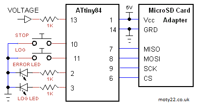
 SD CARD VOLTAGE LOGGING ATtiny84
Logging 5VDC input to the ATtiny ADC. Logs up to 65,000 readings to a TXT file on a SD Card formatted FAT32, cards can be SD or SDHC (1 to 32GB). ATtiny code finds the file and uses its name to set the log interval time. After the code reads 36 voltage readings it calculates the voltage and convert it to text and writes it into single sector on the card. It's repeated for up to 65,000 readings. Log LED blinks when reading is taken. When pressing Stop the new length of the file is written to the file descriptor on the FAT32 location table, so the file length is truncated to the size of the data.
Log pushbutton starts the logging. Interval time is 1 to 255 seconds, it is set by the text file name. The name must have 3 numbers for example 031 (31 seconds) and txt extension. The text file copied to the root directory of the card has to be 1MB or larger, it allocates enough sectors to write the log data.
ATtiny can be programmed using Arduino IDE and Arduino as ISP, see Technical Tips Burning bootloader with setting "Clock Source 8MHz(internal)" and Pin Mapping: "Clockwise".
TO SETUP THE CARD
Format the card with FAT32.
On your PC take any file with the size of 1MB or larger and rename it to 3 digits number (001 to 255) that are the interval time in seconds between readings and txt extension, for example "031.txt" (31 seconds) .
Copy the file to the root folder of the card with no other files added.
 USB FLASH CH376 VOLTAGE LOGGING
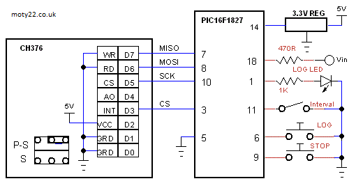
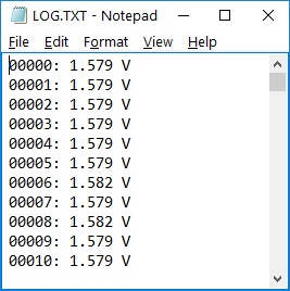
Logs up to 2,000 voltage readings to a TXT file on a USB Flash formatted FAT32. The CH376 writes to the USB storage after every reading. the interval time is 1 second and can be set to 1 minute by the Interval switch. Data is written to a text file named LOG.TXT.
Button LOG starts the logging after creating the file LOG.TXT (32KB), if the file exists it replaced. pressing STOP stops the logging and fills up the rest of the file with spaces, after the LOG LED turnes off the USB memory can be removed.
The CH376 inputs must be 3.3V logic so the PIC VCC is 3.3V. The supply to the USB board is 5V. The board contains 3.3V regulator and that voltage can be used to power the PIC or external 3.3V regulator can be used. The analog input is 0 to 3.3V and accurate as the 3.3V supply. Regulator from eBay: https://www.ebay.co.uk
P-S link on the board is set to S (Serial).
OLED TEMPERATURE LOGGING USING DS18B20 SENSOR
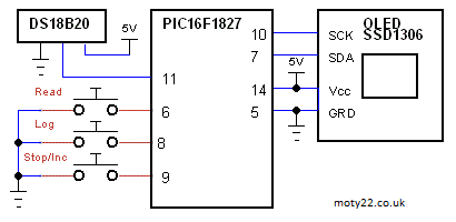
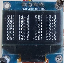
Logging temperature from sensor DS18B20 -55 to 125 deg C. OLED display, 128x64, 0.96", SSD1306, I2C. Up to 96 (48 for PIC16F628A) temperiture readings can be logged, 16 per page. Each reading is stored in 2 bytes in the EEPROM of the PIC. Each log is displayed with number of log followed by temperature. PIC16F628A drives the OLED by software I2C.
On power up the interval time of logging is displayed in seconds, press button Stop/Inc to increase the time, 255 seconds max. To start logging press Log button and Stop/Inc to stop logging. Pressing Read button displays 16 readings, press Read to read next page.
OLED VOLTAGE LOGGING ATtiny85/45
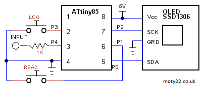
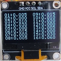
Logging voltage 0-5.115V at 5V supply. OLED display, 128x64, 0.96", SSD1306, I2C. Up to 96 temperiture readings can be logged, 16 per page. Each reading is stored in 2 bytes in the EEPROM. Each log is displayed with number of log followed by voltage.
On power up the interval time of logging is displayed in seconds, press button READ to increase the time, 255 seconds max. To start logging press LOG button. Pressing READ button displays 16 readings, press Read to read next page.
Sketch includes a lib tinyI2C that can be downloaded from GitHub: https://github.com/
ATtiny can be programmed using Arduino IDE and Arduino as ISP, see Technical Tips Burning bootloader with setting "Clock Source 4MHz(internal)". ATtiny85 or ATtiny45 can be used.
VOLTAGE LOGGING TO 24C512 EEPROM
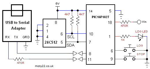
Logging up to 32K voltage readings to 65K EEPROM using PIC16F1827 and 24C512. Connecting the PIC to a PC using USB to Serial converter module Visual Studio app reads the logged data and create a text file. Pressing LOG button starts the logging and STOP button stops and resets the readings counter. When the PC requests the data only the readings till STOP are sent.
The port number can be found in DEVICE MANAGER. Interval time can be 1 to 254 seconds, clicking UPDATE stores the interval time in the PIC eeprom, when the PIC starts it reads the interval time from the PIC eeprom. When clicking Create File the PIC reads the 24C512 and sends the readings to the PC via USB to Serial Adapter. The PC create a text file in the path written in the text box.
App code and EXE file are included. Sampling time can be set up to 2 million seconds. SAVE button saves the reading to a file log.txt in the folder of the app. COPY button copy the log text to the clipboard.
5V supply to the sensor and the PIC are from the 5V output of the USB to Serial module.
USB to Serial from eBay: https://www.ebay.co.uk/
 PC TEMPERATURE LOGGING USING DS18B20 SENSOR
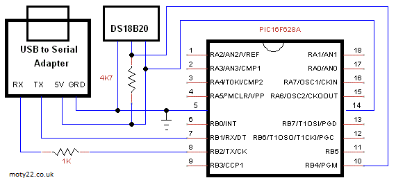
Visual Studio app logging temperature from sensor DS18B20 -55 to 125 deg C. The PIC connects to the PC using USB to Serial converter module. The port number can be found in DEVICE MANAGER. App code and EXE file are included. Sampling time can be set up to 2 million seconds. SAVE button saves the reading to a file log.txt in the folder of the app. COPY button copy the log text to the clipboard.
5V supply to the sensor and the PIC are from the 5V output of the USB to Serial module.
USB to Serial from eBay: https://www.ebay.co.uk/
|
![]()
moty22.co.uk 2008-2025