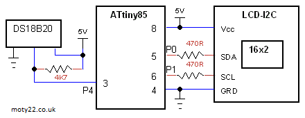
ATTINY45/85 LCD-I2C THERMOMETER SENSOR DS18B20
LCD-I2C 1602 display, ATtiny45 or 85. LCD is driven by software I2C large characters are copied from Arduino. DS18B20 reply is signed integer (2 bytes) the code converts it to 4 decimal digits and a minus sign. Temperature range of -55.0 to 125.0 centigrade.
The sketch can be used by any Arduino if the pin numbers are adapted to the hardware.
ATtiny can be programmed using Arduino IDE and Arduino as ISP, see Technical Tips Burning bootloader with setting "Clock Source 8MHz internal", "LTO enabled".
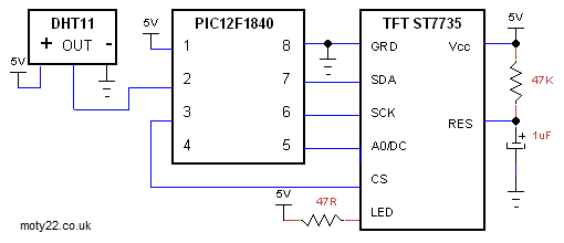
TFT DHT11 SENSOR THERMOMETER PIC12F1840
PIC12F1840, TFT module is a 1.8" 128 X160 pixel and has the driver ST7735 is driven by SPI. DHT11 sensor sends 5 bytes of data for centigrade and humidity, degrees F is calculated.
Temperature range is 0-50 centigrade with resolution of 0.1.
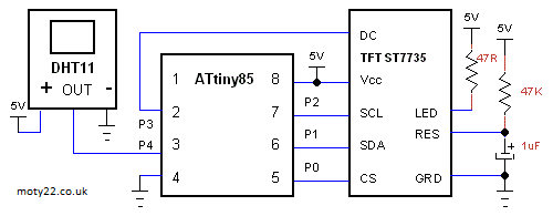
ATTINY85 TFT DHT11 SENSOR THERMOMETER
TFT module is a 1.8" 128 X160 pixel and has the driver ST7735 is driven by SPI. DHT11 sensor sends 5 bytes of data for centigrade and humidity, degrees F is calculated.
Temperature range is 0-50 centigrade with resolution of 0.1.
ATtiny45 can be used too.
ATtiny can be programmed using Arduino IDE and Arduino as ISP, see Technical Tips Burning bootloader with setting "Clock Source 16MHz (PLL)", "LTO enabled".
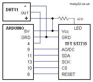
ARDUINO TFT DHT11 SENSOR THERMOMETER
TFT module is a 1.8" 128 X160 pixel and has the driver ST7735 is driven by SPI. DHT11 sensor sends 5 bytes of data for centigrade and humidity, degrees F is calculated.
Temperature range is 0-50 centigrade with resolution of 0.1.
Sketch and circuit are for Uno, Nano and Nano with ATtiny88.
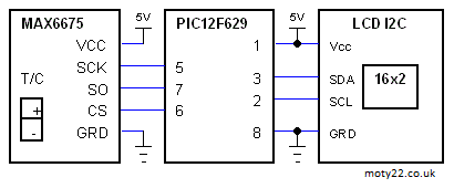
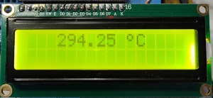
LCD-I2C THERMOCOUPLE 1023 °C PIC12F629
MAX6675 K type thermocouple module. 16x2 LCD display with I2C add-on board. Temperature range is 0-1023 °C with resolution of 1/4 degree. The MAX6675 is interfaced by software SPI, it sends 2 bytes of data.
MAX6675 can be bought from eBay: https://www.ebay.co.uk/
The LCD module has to be HD44780 compatible.
LCD-I2C THERMOCOUPLE 1023 °C ATtiny13
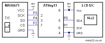
MAX6675 K type thermocouple module. 16x2 LCD display with I2C add-on board. Temperature range is 0-1023 °C with resolution of 1/4 degree. The MAX6675 SPI is interfaced by software SPI, it sends 2 bytes of data. Attiny25/45/85 can be used too, same sketch and circuit.
ATtiny25/45/85 can be programmed using Arduino IDE and Arduino as ISP, see Technical Tips Burning bootloader with setting "Clock Source 4MHz (internal)" and Pin Mapping : "Clockwise".
ATtiny13 can be programmed using Arduino IDE and Arduino as ISP. Use these instructions https://www.electronics-lab.com/ with the setting : 9.6MHz, no millis no tone, LTO enabled.
MAX6675 can be bought from eBay: https://www.ebay.co.uk/
The LCD module has to be HD44780 compatible.
LCD OVEN TEMPERATURE CONTROLLER 1023 °C ATtiny84
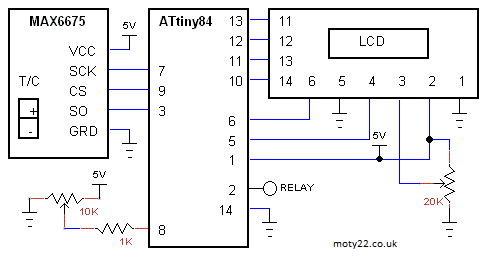
MAX6675 K type thermocouple module. 16x2 LCD display. Temperature range is 0-1023 °C with resolution of 1/4 degree. Temperature is set by 10K potentiometer. Hysteresis is +/- 5 degrees. The MAX6675 SPI is interfaced by software because ATtiny84 can't drive SPI MODE2, it sends 2 bytes of data. Attiny44 can be used too, I didn't test it though.
Relay output is to drive a relay or a solid state relay to power the heating.
ATtiny can be programmed using Arduino IDE and Arduino as ISP, see Technical Tips Burning bootloader with setting "Clock Source 4MHz (internal)" and Pin Mapping : "Clockwise".
MAX6675 can be bought from eBay: https://www.ebay.co.uk/
The LCD module has to be HD44780 compatible.
  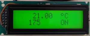
LCD LARGE CHARACTERS THERMOMETER
DS18B20 sensor. 16x2 LCD display, large chars are from Arduino, the code creates shapes stors them in the LCD RAM and uses them to build the characters. Temperature range is -55.0 to 125.0 °C . DS18B20 reply is signed integer (2 bytes) the code converts it to 4 decimal digits and a minus sign.
The LCD module has to be HD44780 compatible.
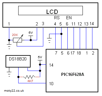 
LCD DHT11 TEMPERATURE HUMIDITY
DHT11 sensor. 16x2 LCD display. Temperature range is 0 to 50.0 °C . DHT11 reply is 5 bytes (40 bits), 2 for temperature and 2 for humidity. Degrees F is calculated.
The LCD module has to be HD44780 compatible.
  
LCD OVEN TEMPERATURE CONTROLLER 1023 °C
MAX6675 K type thermocouple module. 16x2 LCD display. Temperature range is 0-1023 °C with resolution of 1/4 degree. Temperature is set by UP and DOWN buttons. Hysteresis is +/- 5 degrees. There is a 20 seconds delay between ON and OFF of the OUTPUT for relay drive in purpose to increase the life of the relay. The MAX6675 SPI sends 2 bytes of data.
MAX6675 can be bought from eBay: https://www.ebay.co.uk/
The LCD module has to be HD44780 compatible.
  
LCD THERMOCOUPLE THERMOMETER 1023 °C
Thermometer using
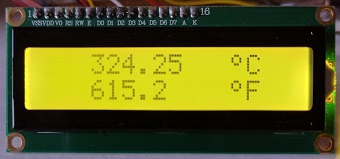
MAX6675 K type thermocouple module. 16x2 LCD display. Temperature range is 0-1023 °C with resolution of 1/4 degree, degrees F is calculated. The MAX6675 SPI sends 2 bytes of data.
Software is for PIC16F1827 and PIC16F628A, circuit is for both PICs.
MAX6675 can be bought from eBay: https://www.ebay.co.uk/
The LCD module has to be HD44780 compatible.
You are free to use the circuit diagram and the code with no
limitations.
|
![]()
moty22.co.uk 2008-2025