|
MULTI TUNE SD DOORBELL
ATtiny85/45
Project using SD card that plays different tunes. When RING button is pressed the next tune is played.
The firmware works for SDHC/SD cards up to 32GB.
The software has the functions needed to read SD card formatted in FAT32. The software can play only PCM 22.050KHz, 8 bits, mono. The bytes from the file are streamed to PWM
generator. The PWM
gives 32KHz wave with duty cycle modulated to the audio amplitude. The 4420 drives the speaker.
SD card interfaces the microcontroller in SPI mode. Reading data is in multi-blocks.
The software searches for files entries in the root directory only.
ATtiny can be programmed using Arduino IDE and Arduino as ISP, see Technical Tips Burning bootloader with setting "Clock Source 8MHz(internal)", this makes the CPU working at frequency of 8MHz.
To power the circuit from 3.7V battery use Micro SD Card Adapter that can be soldered, see Technical Tips. SD card works on 3.6V max, for 5V supply the Micro SD Card Adapter must be used. Powering the SD card and the ATtiny with 3.3V and powering the 4420 with voltage up to 12V will produce louder ring.
4420 is a 6 amp mosfet driver. IC's that can be used are: TC4420, MCP1406, MAX4420. These are very similar and pins are identical.
TO SET UP THE CARD:
Create sound files type .wav using PC.
Name the file with short name, 5 characters max, i.e. 1.wav.
Save the files in PCM format 22.050KHz, 8 bits, mono.
Format the card with FAT32.
Add the files to the root directory
of the card (don't use a subdirectory).

 MULTI TUNE SD DOORBELL
A PIC12F1822 project using SDHC card that plays different tunes. When RING button is pressed the next tune is played.
The firmware works for SDHC cards 2-32GB only.
The software has the functions needed to read SDHC card formatted in FAT32. The software can play only PCM 22.050KHz, 8 bits, mono. The bytes from the file are streamed to PWM
generator. The PWM
gives 32KHz wave with duty cycle modulated to the audio amplitude. The 4420 drives the speaker.
SD card interfaces the microcontroller in SPI mode. Reading data is in multi-blocks.
The software searches for files entries in the root directory only.
To power the circuit from 3.7V battery use Micro SD Card Adapter that can be soldered, see Technical Tips. SD card works on 3.6V max, for 5V supply the Micro SD Card Adapter must be used. Powering the SD card and the ATtiny with 3.3V and powering the 4420 with voltage up to 12V will produce louder ring.
4420 is a 6 amp mosfet driver. IC's that can be used are: TC4420, MCP1406, MAX4420. These are very similar and pins are identical.
TO SET UP THE CARD:
Create sound files type .wav using PC.
Name the file with short name, 5 characters max, i.e. 1.wav.
Save the files in PCM format 22.050KHz, 8 bits, mono.
Format the card with FAT32.
Add the files to the root directory
of the card (don't use a subdirectory).

ARDUINO SD DOORBELL
A doorbell project for Arduino with ATMEGA328P device.
The firmware works for SD or SDHC cards 1-32GB. The code detects whether the card is SD or SDHC and selects the proper addressing system for the card. The quality of the audio is reasonable.
The software has the functions needed to read SD/SDHC card formatted in FAT32. The software can play only PCM 22.050KHz, 8 bits, mono. The bytes from the file are streamed to PWM
generator. The PWM
gives 64KHz wave with duty cycle modulated to the audio amplitude. A 2 transistors buffer drives the speaker.
SD card interfaces the microcontroller in SPI mode. Reading data is in multi-blocks.
The Error LED indicates error of communication with the SD card.
The software searches for files entries in the root directory only.
TO SET UP THE CARD:
Create sound file type .wav using PC.
Name the file with short name, 8 low case characters max.
Save the file as 22.050KHz, 8 bits, mono.
Format the card with FAT32.
Add the files to the root directory
of the card (don't use a subdirectory).
 
ARDUINO EEPROM DOORBELL
A doorbell project for Arduino Uno ,Nano or ATtiny85/45.
The EEPROM 24C512 is 512Kbits and it can store up to 3 seconds wave file
of 22.050KHz, 8 bits, mono.
Uno, Nano
The Arduino reads the ROM bytes in a
sequential read mode and stream each byte to the PWM generator at a rate of about 22
KHz.
The I2C bus works at 200 KHz for the purpose of managing to process
22 Kbits per second. Changing the bus frequency changes the speed of the
sound.
The I2C lib doesn't have a function for sequential read, so I added a routine.
ATtiny
Sketch includes a lib tinyI2C that can be downloaded from GitHub: https://github.com
ATtiny can be programmed using Arduino IDE and Arduino as ISP, see Technical Tips Burning bootloader with setting "Clock Source 16MHz(PLL)", this makes the CPU working at frequency of 16MHz.
Included in the software is HEX file for the EEPROM. It has a
sound of a rooster crowing.
To convert
sound file to hex:
Convert sound file to .wav PCM
22.050KHz, 8 bits, mono.
Use either the CH341 programmer or Arduino programmer below to load the EEPROM, or change the file name extension from wav to bin and load the
bin file
to the EEPROM Programmer or PICKIT.
 
Circuit Description
See also Technical Tips
Transistors can be equivalents to the ones marked.
pin 7 of 24C512 can be connected to 5V to
inhibit writing.
EEPROM DOORBELL PIC16F1827 / PIC12F1822
The EEPROM 24C512 is 512Kbits and it can store up to 3 seconds wave file
of 22.050KHz, 8 bits, mono.
The PIC reads the ROM bytes in a
sequential read mode and stream each byte to the PWM generator at a rate of about 22
KHz. The I2C bus works at 400 KHz for the purpose of managing to process
22 Kbits per second. Changing the bus frequency changes the speed of the
sound.
Included in the software is HEX file for the EEPROM. It has a
sound of a rooster crowing.
To convert
sound file to hex do this:
Convert sound file to .wav PCM
22.050KHz, 8 bits, mono,
Use the CH341 or Arduino project below to load the EEPROM, or change the file name extension from wav to bin and load the
bin file
to the EEPROM Programmer or PICKIT.
 
Circuit Description
See also Technical Tips
Transistors can be equivalents to the ones marked.
pin 7 of 24C512 can be connected to 5V to
inhibit writing.
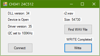
EEPROM 24C512 CH341 PROGRAMMER
Programmer to upload WAV file to I2C EEPROM 24c512. WAV files up to 65,536 bytes can be uploaded and played by Arduino or PIC Doorbell above projects. Writing the memory takes up to 10 seconds. The app is in Visual Basic VS2010.
Sound files have to be converted to wav type files PCM 22,050 KHz 8 bit Mono.
In the app click Connect, find the file to upload and click Write, wait until indicated that writing is completed (up to 10 seconds).
EEPROM 24C512 ARDUINO PROGRAMMER
Programmer to upload WAV file to I2C EEPROM 24c512. WAV files up to 65,536 bytes can be uploaded and played by Arduino or PIC Doorbell above projects. Writing the memory takes up to 20 minutes. The app is in Visual Basic VS2010.
Sound files have to be converted to wav type files PCM 22,050 KHz 8 bit Mono.
In the app click Connect, find the file to upload, choose if you want to fill up with silent beyond the end of the file, click Write, wait until indicated LOADED
 
PIC16F876A EEPROM DOORBELL
The EEPROM 24C512 is 512Kbits and it can store up to 3 seconds wave file
of 22.050KHz, 8 bits, mono.
The PIC reads the ROM address 0 first
and then reads bytes in a
sequential read mode and stream each byte to the PWM generator at a rate of about 22
KHz. The I2C bus works at about 300 KHz for the purpose of managing to process
22 Kbits per second. Changing the bus frequency changes the speed of the
sound.
I use resistors DAC (Digital to Analogue Converter) because the
PIC's PWM is too slow.
It is easy to get 6 seconds sound at 11.025 KHz
wave file by changing the crystal osc to 4 MHz.
Included in the software is HEX file for the EEPROM. It has a
sound of a rooster crowing, I use this one in my house.
After programming the PIC16F876A connect pin 1 (reset) to 5V.
To convert
sound file to hex do this:
Convert sound file to .wav PCM
22.050KHz, 8 bits, mono
Change the file name extension from wav to bin.
Load the
bin file
to the EEPROM Programmer, I used PICKIT2.
To remove the file header
you can change the first 44 bytes to zeros or remove them using any BIN
FILE EDIT software.
Export the file from the programmer as HEX.

Circuit Description
See also Technical Tips
BC337 and BC307 switch on the audio amp for the duration of the
ring. You can omit this switch and connect the amp directly to the supply if the
hiss noise from the amp isn't a problem.
pin 7 of 24C512 can be connected to 5V to
inhibit writing.
1R resistors can be 10K or 7.5K and 2R 20K or 15K. Values
aren't critical, 20% error is acceptable. |