|
PIC12F1822 WITH USB TO UART OSCILLOSCOPE FOR PC
Low frequency oscilloscope, bandwidth is DC to 5KHz. Max sampling rate is 50,000 samples per second. The USB to UART (Serial) Adapter communicates between the PIC and the PC. eBay
The PIC code sends 62 bytes of input sampling to form one screen, screen sampling is taken every 0.5 second. The PC sends 1 byte that relates to time selected in the app..
The PC app is in VS2010, code and exe file are included.
The Analogue Comparator of the PIC (pins 6, 7) is used to detect zero crossing of input signal, it triggers start of sampling the trace when signal is rising.
The screen is constructed from 62 sampling. The ADC reads the input at resolution of 10 bits and the MSB 8 bits are used and the dote position is calculated.
100K Resistors bias the input to a voltage of middle of the screen, use them if your input is AC. The input is at pin 5 , for DC input bypass 1uF cap.
  
PIC16F1827 / ARDUINO LOGIC ANALYZER FOR PC
Logic analyzer 4 channels for frequencies up to 20KHz. PIC is connected to PC via USB to UART (Serial) Adapter eBay , Arduino Uno or Nano are connected to USB directly (no need for adapter). PIC or Arduino use Visual Studio 2010 app to display the logic. Waveforms aren't accurate for frequencies over 20KHz due to the speed of the microcontroller.
The code sends 64 bytes of input sampling to form one screen, screen sampling is taken every 1 second. The PC sends 1 byte that relates to time selected in the app..
The PC app is in VS2010, code and exe file are included.
Arduino inputs are at pins 8,9,10,11 when channel 1 is at pin 8.
 
ARDUINO OSCILLOSCOPE FOR PC
Low frequency oscilloscope, bandwidth is DC to 25KHz. Max sampling rate is 50,000 samples per second. Arduino Uno or Nano can be used. The input is to pin A0 of the Arduino which connected to PC via USB.
The PC app is in VB6 and VS2010, code and exe file are included.
The Arduino software is mostly in C code in purpose to speed up the ADC on expense of conversion accuracy. For lower frequencies a delay for each sample gives slower sweep. Input is DC or AC not acceding 5V.
The Analogue Comparator of the Arduino (pins 6, 7) is used to detect zero crossing of input signal, it triggers start of sampling the trace when signal is rising.
The screen is constructed from 62 sampling. The ATMEGA ADC reads the input at resolution of 10 bits and the MSB 8 bits are used and the dote position is calculated.
Resistors bias the input to a voltage of middle of the screen, use them if your input is AC.
OLED OSCILLOSCOPE PIC12F1822
OLED low frequency oscilloscope, bandwidth is DC to 5KHz. Max sampling rate is 50,000 samples per second. An oscilloscope with these specifications has limited use, but it is a good exercise in using OLED display. Software trigger starts the sampling when the input signal crosses zero. Input tolerates 5V max.
Oled is 0.96" I2C SSD1306 driver.
The screen is constructed from 64 sampling. The ADC reads the input at resolution of 10 bits. The MSB 8 bits are used and the dote position is calculated.
SWEEP sets the X timing by changing the delay between samplings.
OLED OSCILLOSCOPE ATtiny85
OLED low frequency oscilloscope, bandwidth is DC to 5KHz. Max sampling rate is 50,000 samples per second. An oscilloscope with these specifications has limited use, but it is a good exercise in using OLED display. Software trigger starts the sampling when the input signal crosses zero. Input tolerates 5V max.
ATtiny85 or ATtiny45 can be used. Oled is 0.96" I2C SSD1306 driver.
The screen is constructed from 64 sampling. The ADC reads the input at resolution of 10 bits. The MSB 8 bits are used and the dote position is calculated.
SWEEP sets the X timing by changing the delay between samplings.
ATtiny can be programmed using Arduino IDE and Arduino as ISP, see Technical Tips Burning bootloader with setting "Clock Source 4MHz internal".

ARDUINO OLED OSCILLOSCOPE
OLED low frequency oscilloscope, bandwidth is DC to 20KHz. Max sampling rate is 50,000 samples per second. An oscilloscope with these specifications has limited use, but it is a good exercise in using OLED display.
Arduino Uno or Nano can be used. Oled is 0.96" I2C SSD1306 driver.
The screen is constructed from 64 sampling. The ATMEGA ADC reads the input at resolution of 10 bits. The MSB 8 bits are used and the dote position is calculated.
Switch is on for input frequency below 100Hz.
Resistors bias the input to a voltage of middle of the screen, use them if your input is AC.

ARDUINO TFT OSCILLOSCOPE
LCD TFT low frequency oscilloscope, bandwidth is DC to 5000Hz. Max sampling rate is 40000 samples per second. An oscilloscope with these specifications has limited use, but it is a good exercise in using LCD TFT. Arduino can be Uno or Nano.
The screen is constructed from 33 lines. The ADC reads the input at resolution of 10 bits, the MSB 8 bits are stored in the RAM and then transmitted to the LCD RAM by 4 wires SPI.
The Sweep time is selected by the 10K pot, the ADC converts the pot voltage to digital value.
LCD TFT modules has the driver ST7735, 160x128 pixels, 1.8 inch.
TFT OSCILLOSCOPE PIC16F690
LCD TFT low frequency oscilloscope, bandwidth is DC to 500Hz. Max sampling rate is 16000 samples per second. An oscilloscope with these specifications has limited use, but it is a good exercise in using LCD TFT. Arduino can be Uno or Nano.
The screen is constructed from 33 lines. The ADC reads the input at resolution of 10 bits, the MSB 8 bits are stored in the RAM and then transmitted to the LCD RAM by 4 wires SPI.
The Sweep time is selected by the 10K pot, the ADC converts the pot voltage to digital value.
LCD TFT modules has the driver ST7735, 160x128 pixels, 1.8 inch.

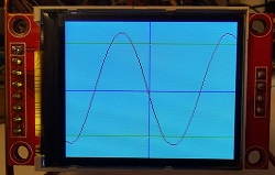
TFT OSCILLOSCOPE
LCD TFT is digital display at its best, it displays versatile clear picture. The picture is built by entering the address and the color of a pixel or rectangle, so it's simple to use too.
LCD TFT low frequency oscilloscope, bandwidth is DC to 1000Hz. Max sampling rate is 16000 samples per second. An oscilloscope with these specifications has limited use, but it is a good exercise in using LCD TFT.
The screen is constructed from 80 sampling. The ADC reads the input at resolution of 10 bits. The MSB 8 bits are stored in the pic RAM and then transmitted to the LCD RAM by 4 wires SPI.
The time selector has 100ms per screen, 10ms and the third position is about 5ms. The trigger is done by software and can be switched off.
LCD TFT modules vary depending on the drive IC. The module in the project has the driver ST7735. I bought this module directly from China because the price was more sensible.
Code was written on MPLAB and compiled with the free HI TECH C compiler V9.80
  
Circuit Description
See also Technical Tips
Pin 2 is the analogue input. Input voltage range is 0 to 5V absolute max,
voltage outside this range can latch the input or even permanently damage the IC.
The clock is 8MHz by the crystal osc.
The module in the project has the driver ic ST7735 . |