|
For low input signal use high speed comperator: eBay
16MHz PIC16F1827 LED FREQUENCY COUNTER
Counter based on PIC16F1827 .
Included C code and circuit diagram. Input is a TTL level. The counting repeats every about 1sec. The 8MHz crystal is for generating accurate time base for counting the input frequency. The LED module doesn't flicker, LED brightness can be set in the code, value can be 0-15. The 7 segment LED module is driven by 3 lines of the pic SPI.
TMR0 input can count frequency up to 50MHz if the signal is 50% duty cycle. If the duty cycle is 10% then the max frequency is 10MHz.
TMR0 prescaler divides by 2 to increase the input
frequency range to 16 MHz.
The counter measure the frequency for 0.1sec first, if the frequency is greater than 2MHz TMR0 prescaler divides by 2 to increase the input
frequency range to 16MHz with resolution of 2Hz, if the frequency below 2MHz TMR0 is set for no prescaling and the measurment is with resolution of 1Hz.
Software includes PIC code. You are free to use the circuit diagram and the software with no
limitations.
 
 8 DIGITS LED DISPLAY MAX7219 16MHz FREQUENCY COUNTER
Counter based on PIC16F628A . Input is a TTL level. The counting repeats every about 1 sec. The 20MHz crystal is for generating accurate time base for counting the input frequency. The LED module doesn't flicker, LED brightness can be set in the code, value can be 0-15.
PIC16F628A TMR0 input can count frequency up to 16MHz if the signal is 50% duty cycle. If the duty cycle is 10% then the max frequency is 10MHz.
The counter measure the frequency for 0.1sec first, if the frequency is greater than 2MHz TMR0 prescaler divides by 4 to increase the input
frequency range to 16MHz with resolution of 4Hz, if the frequency below 2MHz TMR0 is set for no prescaling and the measurment is with resolution of 1Hz.
The 7 segment LED module is driven by 3 lines, the pic generates a software SPI.

ATtiny84 LED DISPLAY MAX7219 6MHz FREQUENCY COUNTER
Counter with ATtiny84 driving MAX7219 8 digits 7 segment module.
Included INO file and circuit diagram. Input is a TTL level. The counting repeats every about 2 sec. The LED module doesn't flicker, LED brightness can be set in the code, value can be 1-15. The code suppose to work with ATtiny44/24 too, I didn't test it though.
The ATtiny generates an accurate 1 second time base using timer1. Timer0 is 8 bit counter, overflows of the counter are counted by 2 registers and used to calculate the frequency.
ATtiny can be programmed using Arduino IDE and Arduino as ISP, see Technical Tips Burning bootloader with setting "Clock Source 16MHz (external)" and Pin Mapping : "Clockwise".
Max7219 lib is used: https://github.com/
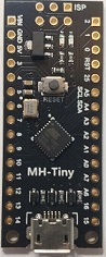
ATtiny88 LED DISPLAY MAX7219 6MHz FREQUENCY COUNTER
Counter with low cost Arduino Nano with ATtiny88 driving MAX7219 8 digits 7 segment module.
Input is a TTL level. The counting repeats every about 2 sec. The LED module doesn't flicker, LED brightness can be set in the code, value can be 1-15. Decimal Point link switches on decimal points for MHz and KHz.
The ATtiny generates an accurate 1 second time base using timer1. Timer0 is 8 bit counter, overflows of the counter are counted by 2 registers and used to calculate the frequency. MAX7219 is driven by SPI.
ATttiny can be programmed using Arduino IDE. Use these instructions https://handsontec.com/>
ARDUINO LED DISPLAY MAX7219 6MHz FREQUENCY COUNTER
Counter based on Arduino Uno or Nano.
Included INO file and circuit diagram. Input is a TTL level. The counting repeats every about 1 sec. The LED module doesn't flicker, LED brightness can be set in the code, value can be 1-15.
The Arduino generates an accurate 1 second time base for the counter by
cascading timer0 and timer2. The link between digital inputs 3 and 4
connects the output of timer2, 250 Hz, to input of timer0. The software
waits for the output of timer0 to go positive to start the count of
frequency input to timer1. Timer1 is a 16 bits timer, it overflows at the
count of 2 power of 16, that in turn advances over-flow register. At the end
of the 1 second the 16 bit register is recorded.
Max7219 lib is used: https://github.com/
Arduino modules have either 16MHz crystal with 50 ppm tolerance or 16MHz ceramic resonator with tolerance of 0.5% and temperature stability of 0.2%. The crystal is more accurate.

4 DIGITS 6MHz FREQUENCY COUNTER ATtiny88
Counter based on low cost Nano ATtiny88.
Input is a TTL type. The counting repeats every about 2 sec. The 3 LEDs display MHz or KHz or Hz unites, right of the decimal point is fruction of the unit.
During the 1 second period of counting the display is switched off. TIMER1 used for generating accurate time base for counting the input frequency, TIMER0 is the counter.
The 7 segment LED is common cathode, cc1 is the common cathode of the digit on the left. The 7 segment LED I used are 5621AS.
ATttiny can be programmed using Arduino IDE. Use these instructions https://handsontec.com/
 
8 DIGITS 50MHz FREQUENCY COUNTER
Counter based on PIC16F628A .
Included C code and circuit diagram. Input is a TTL type. The counting repeats every about 5 sec. The 32K crystal is for generating accurate time base for counting the input frequency. The MCU uses the 4MHz internal oscillator. During the 1 second period of counting the display is switched off.
PIC16F628A TMR0 input can count frequency up to 50 MHz if the signal is 50% duty cycle. If the duty cycle is 10% then the max frequency is 10MHz.
TMR0 can count up to 2MHz , the prescaler is used to increase the input
frequency range to 64MHz. Frequencies up to 1MHz are counted with
resolution of 1Hz, frequencies above 1MHz are counted at resolution of
32Hz.
I tested the counter up to 2MHz only, I don't have the means to do
better tests.
The 7 segment LED is common cathode, cc8 is the common cathode of the digit on the left. 100 ohm resistor for the segments is for a current of 20mA, the max output current of the pic is 25mA, so if you change the resistors make sure you don't exceed this current.
To drive 8 digits from 5 outputs I used a system of 2 out of 5 that gives up to 10 outputs by AND gating to outputs. I used one output to drive the base of the transistor and the other a diode. the emitter of the transistors are elevated by 0.7V by a diode, this to make sure they are switched off when the diode at the base is low. It is possible to reduce the number of digits by deleting them and by deleting the lines in the code that drives the digits.
Software includes PIC code. You are free to use the circuit diagram and the software with no
limitations.

Circuit Description
See also Technical Tips
All transistors are BC337 or equivalent.
Total 5V supply current can reach145mA.
The 8 digits display is common cathode, for red LEDs the 7 resistors of 100 ohms enable current of 20 mA total, average of 2.5 mA through each segment which is on for eighth of the time. To increase the brightness the resistors can be decreased to max current of 25 mA. The seven segments, a to g, of one digit are linked to the corresponding seven segments in the other digits. cc8 is the common cathode of the digit on the left.
The 8 digits are multiplexed by 5 pic's outputs, for each group of 2 out of 5 a digit is switched on. The diode to ground from the emitters is to insure full switch off when the gating diode at the base is low.
4 DIGITS 16MHz FREQUENCY COUNTER
Counter based on PIC16F628A .
Included C code and HEX file. Input is a TTL type. The counting repeats every about 3 sec. During the 1 second period of counting the display is switched off. The 20 MHz crystal is for generating accurate time base for counting the input frequency. When the frequency is up to 2MHz the resolution is 1Hz, above 2MHz resolution is 4Hz.
The 7 segment LED is common cathode. The 7 segment LED I used are 5621AS. 3 LEDs lamps are used to indicate units of the frequency displayed.
The 8 resistors of 1K enable current of 3.5 mA through each segment which is on for 1/4 of the time. The seven segments, A to G and DP of one digit are linked to the corresponding seven segments in the other digits. cc1 is the common cathode of the digit on the left.
|