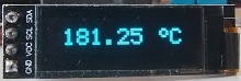
ATTINY13/25/45/85 OLED THERMOCOUPLE THERMOMETER 1023 °C
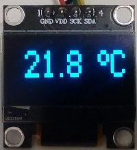
OLED display, 128x64 0.96" or 128x32 0.91", SSD1306, I2C with ATtiny13 or ATtiny25/45/85 and MAX6675 K type thermocouple module. MAX6675 is driven by software (bit banging) SPI. The MAX6675 SPI sends 2 bytes of data. OLED is driven by software I2C.
Temperature range is 0-1023.75 centigrade with resolution of 0.25 degree.
The sketch can be used without any changes for ATtiny13/25/45/85
ATtiny13 can be programmed using Arduino IDE and Arduino as ISP. Use these instructions https://www.electronics-lab.com/ with the setting : 9.6MHz, no millis no tone, LTO enabled.
ATtiny can be programmed using Arduino IDE and Arduino as ISP, see Technical Tips Burning bootloader with setting "Clock Source 8MHz internal", "LTO enabled".
MAX6675 can be bought from eBay: https://www.ebay.co.uk
PIC12F629 OLED THERMOCOUPLE THERMOMETER 1023 °C
OLED display 128x32 0.91", SSD1306, I2C with PIC12F629 and MAX6675 K type thermocouple module. MAX6675 is driven by software (bit banging) SPI. The MAX6675 SPI sends 2 bytes of data. OLED is driven by software I2C.
Temperature range is 0-1023.75 centigrade with resolution of 0.25 degree.
ATTINY13/25/45/85 OLED DHT11 THERMOMETER
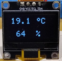
OLED display, 128x64 0.96" or 128x32 0.91", SSD1306, I2C with ATtiny13 or ATtiny25/45/85 and DHT11 module. OLED is driven by software I2C. DHT11 reply with 5 bytes of data 3 are used to display temperature and humidity.
The sketch and circuit can be used without any changes for ATtiny13/25/45/85
ATtiny13 can be programmed using Arduino IDE and Arduino as ISP. Use these instructions https://www.electronics-lab.com/ with the setting : 9.6MHz, no millis no tone, LTO enabled.
ATtiny25/45/85 can be programmed using Arduino IDE and Arduino as ISP. Use these instructions https://gist.github.com/ with the difference of burning bootloader with setting "Clock Source 8MHz internal", "LTO enabled".
ATTINY25/45/85 OLED THERMOMETER SENSOR DS18B20
OLED display, 128x64 0.96" or 128x32 0.91", SSD1306, I2C with ATtiny25/45/85 . OLED is driven by I2C. DS18B20 reply with 2 bytes of data for temperature range of -55 to 125 centigrade.
Sketch includes a lib for tinyI2C that can be downloaded from GitHub: https://github.com/
ATtiny can be programmed using Arduino IDE and Arduino as ISP, see Technical Tips Burning bootloader with setting "Clock Source 8MHz internal", "LTO enabled".
ATTINY85 OLED THERMOCOUPLE THERMOMETER 1023 °C
OLED display, 128x64, 0.96", SSD1306, I2C with ATtiny85 or ATtiny45 and MAX6675 K type thermocouple module. MAX6675 is driven by software (bit banging) SPI. The MAX6675 SPI sends 2 bytes of data. Sketch includes a lib for tinyI2C that can be downloaded from GitHub: https://github.com/
Temperature range is 0-1023.75 centigrade with resolution of 1/4 degree.
ATtiny can be programmed using Arduino IDE and Arduino as ISP, see Technical Tips Burning bootloader with setting "Clock Source 8MHz internal", this makes the CPU working at frequency of 8MHz.
MAX6675 can be bought from eBay: https://www.ebay.co.uk/
 
OLED THERMOCOUPLE THERMOMETER 1023 °C
OLED display, 128x64, 0.96", SSD1306, I2C with PIC12F1822 and MAX6675 K type thermocouple module. MAX6675 is driven by software (bit banging) SPI. The MAX6675 SPI sends 2 bytes of data.
Temperature range is 0-1023.75 centigrade with resolution of 1/4 degree.
MAX6675 can be bought from eBay: https://www.ebay.co.uk/

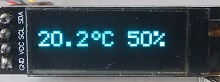
AHT21B OLED TEMPERATUE HUMIDITY
OLED display, 128x64, 0.96", SSD1306, I2C with PIC12F1822 and temperature / humidity sensor AHT21b ranging -40 to 120. The sensor and display share the I2C connection to the PIC. The PIC sends measurement trigger and sensor sends back 1 byte of state, 5 bytes of data for temperatue and humidity and 1 byte CRC. Sensor accuracy is 1% for humidity and 2 degrees for temperature.
For using 0.91", 128x32 Oled 3 changes are needed in the code: change definition of yt to 0, yh to 2 and in void oled_init() change command(0x12) to command(0x22).
Ebay: https://www.ebay.co.uk
  
OLED THERMOMETER PIC12F629
OLED display, 128x64 - 0.96" or 128x32 - 0.91", SSD1306, I2C with PIC12F629 and DS18B20 sensor. Oled is driven by software (bit banging) I2C.
Code includes functions for reading the sensor.
If using 128x32 OLED change code in main() oled_init(64); to oled_init(32); HEX files for both OLEDs are included.
Temperature range is -55 to 100 centigrade.
470 ohm resistors are for attenuating 5V output of the pic to 3.3V input of the OLED.
OLED THERMOMETER HUMIDITY DHT11 PIC12F629
OLED display, 128x64 - 0.96" , SSD1306, I2C with PIC12F629 and DHT11 sensor. Oled is driven by software (bit banging) I2C. Temperature range is 0 to 50.0 centigrade. DHT11 reply with 5 bytes of data 3 are used to display temperature and humidity.
470 ohm resistors are for attenuating 5V output of the pic to 3.3V input of the OLED.
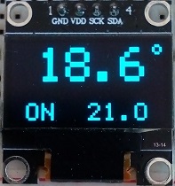
OLED ROOM THERMOSTAT
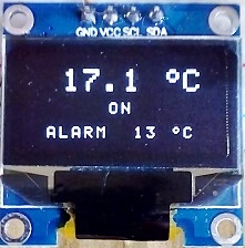
OLED display, 128x64, 0.96", SSD1306, I2C. PIC16F628A Oled is driven by software (bit banging) I2C.
PIC12F1822 uses hardware I2C. Setting the room temperature by 2 buttons.
Output transistor is to drive a relay or directly 24VDC input to a central heating boiler. Hysteresis is 0.5 degree.
Reading the temperature is every second.
OLED module is I2C interface, 4 pins connector. Driver SSD1306. From
ebay: https://www.ebay.co.uk/itm/0-96
OLED THERMOMETER USING DS18B20 DIGITAL SENSOR
Thermometer based on PIC16F876A
and DS18B20 digital sensor. Included C code and circuit diagram. Displays -55 to 125 centigrade. The temperature is read every 1 second. The math is using integers to calculate the degrees and the tenths of degrees are calculated separately.
Output at pin 3 can be used for driving a relay that is on when
temperature is higher than alarm setting. It can be used as a thermostat
or an alarm for over temperature. To set the alarm press SET for 2
seconds, then press DEGREE to set the alarm, then press SET again.
The OLED module is a 0.96" 128 X 64 pixel driven by I2C interface and
using SSD1306 driver IC. The OLED display uses low power LEDs and
suitable for battery operated. Power can be reduced farther by reducing
contrast.
OLED module can be bought from ebay: https://www.ebay.co.uk/itm/0-96
OLED BITMAP
Displaying Bitmap image with PIC16F876A or Arduino on
OLED display module. Included C code and circuit diagram.
To convert image to code:
On a PC
(MS Paint) resize image to 48x48 pixels and save as monochrom bmp.
Download LCD Assistant app from http://en.radzio.dxp.pl//
Set it to Byte
Orientation - Vertical, Pixels/byte - 8. Save file as text file and copy
the bitmap array to the code page.
OLED module is 0.96" 128x64, 4 pins connector I2C interface. Driver IC
is SSD1306.
  
|