SELF
POWERED ADC INTERFACE TO COM PORT
Project
for connecting analogue signal to serial port. Included Visual
Basic VB6 software and a circuit diagram. The MCP3201 is a micro-power
12 bit analogue to digital converter. The conversion selector reads all the 12 bits,
the 10 or 8 MSB and ignores the LSB. With less resolution the reading is more stable. The supply
to the circuit is via the 12V at pin 7 that are switched to logic
high by the software.
The communication to the PC is bit banging the Hardware Controls, the DTR is used for clocking the ADC and the CTS is used for data input.
You can read more about serial interface in http://www.beyondlogic.org/spp/serial.htm
Datasheet for the MCP3201 can be downloaded from here. LTC1285, ADS7822 are direct replacement to MCP3201.
You are free to use the circuit diagram and VB code with no limitations.
 
Circuit Description
See also Technical Tips
MCP3201
Input at pin 2 of the ADC is 0 to 5 volts full range positive
voltage only. The chip over voltage protection is 5V max.
Pin 8 is the 5 V supply to the IC.
Pin 1 is reference voltage for the ADC , it's connected to the 5V and can be connected to an external reference voltage. The reference voltage determents the input voltage span.
Pin 6 is the serial data out of the ADC, BC237 and BC327 are a level shift from 0-5V to -8 to +8V which is the voltage required for the serial connector.
Pin 7 is the clock for reading the data and pin 5 is the Chip Select.
The 22K resistors are for lowering the 12V out of the serial port to 5V level of the ADC.
SERIAL PORT
THERMOMETER
Serial thermometer using
transistor as a temperature sensor and MCP3201. Included
Visual Basic 6 code
and a circuit diagram.
The MCP3201 is a micro-power
12 bit analogue to digital converter. The supply
to the circuit is via the 12V at pin 7 that is switched to logic
high by the software (RTS enabled).
The communication to the PC is bit banging the Hardware Controls, the DTR is used for clocking the ADC and the CTS is used for data input.
NPN transistor with the collector and the base linked makes linear temperature
sensor, the junction voltage changes at 2.25mV/centigrade
with a negative coefficient. For quicker response use a small package
i.e. TO92.
CALIBRATION: The calibration of the sensor and
other components in the circuit is done in the VB application. When you start the VB application for the first time it creates a text file 'cal.txt' in the same folder. The file has 2 numbers that represent the sensor readings at 0 and 100 Centigrade. Because the voltages of different sensors vary it needs recording the voltages of the sensor in use. Record the voltages this way:
1.
Cool the sensor to temperature near zero, ice mixed with water
is 0 centigrade.
2. Click the 0 °C button, the application will update the file 'cal.txt' with a new value of the sensor reading.
3. Use boiling water to heat the sensor to 100 centigrade
4. Click the 100 °C button to update 'cal.txt' file with the new value.
You can read more about serial interface in http://www.beyondlogic.org/spp/serial.htm
Data sheet for the MCP3201 can be downloaded from here. LTC1285, ADS7822 are direct replacement to MCP3201.
VB6 code download. You are free to use the circuit diagram and the VB software with no limitations.
 
Circuit Description
See also Technical Tips
MCP3201
Pin 2 is the analogue input. Input voltage range of +Vref (about 1 V) is equal to digital 4096.
Pin 1 is the +Vref =1V . 10K and 2K7 metal film resistors will give better temperature stability.
Pin 8 is the 5 V supply to the IC. LP2950 is a Low Dropout 5V regulator, you can use either LP2950ACZ-5 or TS2950CT-5 or LM2931Z-5 or equivalent.
Pin 6 is the serial data out of the ADC, BC237 and BC327 are a level shift from 0-5V to -8 to +8V which is the voltage required for the serial connector.
Pin 7 is the clock for reading the data and pin 5 is the Chip Select.
The 22K resistors are for lowering the 12V out of the serial port to 5V level of the ADC.
SENSOR
MTS102 could be hard to find, but any NPN transistor, TO92 or smaller
package will give good response.
SERIAL PORT
THERMOSTAT
Serial thermostat using
transistor as a temperature sensor and MCP3201. Included
Visual Basic 6 code
and a circuit diagram. The MCP3201 is a micro-power
12 bit analogue to digital converter. The supply
to the circuit is from external 12V .
The communication to the PC is bit banging the Hardware Controls, the DTR is used for clocking the ADC and the CTS is used for data input. RTS at pin 7 is the drive for the relay. The relay changes when temperature is more than 0.5 degree from the set temperature.
NPN transistor with the collector and the base linked makes linear temperature
sensor, the junction voltage changes at 2.25mV/centigrade
with a negative coefficient. For quicker response use a small package
i.e. TO92.
CALIBRATION: The calibration of the sensor and
other components in the circuit is done in the VB application. When you start the VB application for the first time it creates a text file 'cal.txt' in the same folder. The file has 2 numbers that represent the sensor readings at 0 and 100 Centigrade. Because the voltages of different sensors vary it needs recording the voltages of the sensor in use. Record the voltages this way:
1.
Cool the sensor to temperature near zero, ice mixed with water
is 0 centigrade.
2. Click the 0 °C button, the application will update the file 'cal.txt' with a new value of the sensor reading.
3. Use boiling water to heat the sensor to 100 centigrade
4. Click the 100 °C button to update 'cal.txt' file with the new value.
You can read more about serial interface in http://www.beyondlogic.org/spp/serial.htm
Data sheet for the MCP3201 can be downloaded from here
VB6 code download. You are free to use the circuit diagram and the VB software with no limitations.

The VB6
thermometer application.
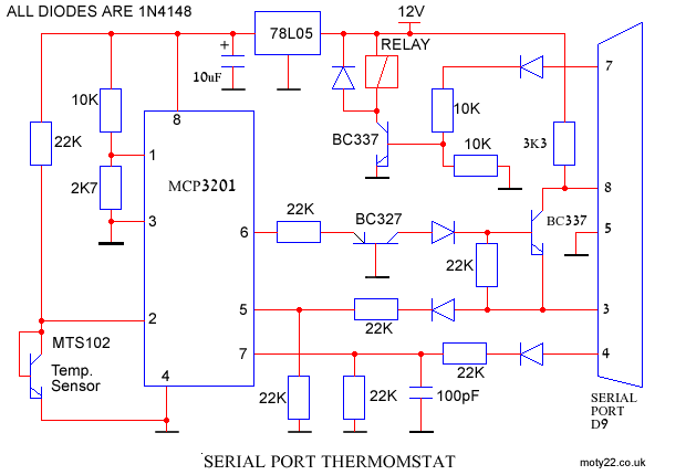
Circuit Description
See also Technical Tips
MCP3201
Pin 2 is the analogue input. Input voltage range of +Vref (about 1 V) is equal to digital 4096.
Pin 1 is the +Vref =1V . 10K and 2K7 metal film resistors will give better temperature stability.
Pin 8 is the 5 V supply to the IC. 78L05 is a 5V regulator, it regulates the 12V external supply that also powers the relay.
Pin 6 is the serial data out of the ADC, BC237 and BC327 are a level shift from 0-5V to -8 to +8V which is the voltage required for the serial connector.
Pin 7 is the clock for reading the data and pin 5 is the Chip Select.
The 22K resistors are for lowering the 12V out of the serial port to 5V level of the ADC.
SENSOR
MTS102 could be hard to find, but any NPN transistor, TO92 or smaller
package will give good response.
SERIAL PORT
INPUTS OUTPUTS
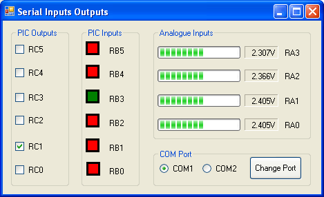
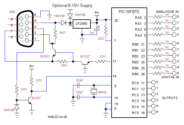
The serial port drives and powers PIC16F870. 4 analogue inputs, 6 digital inputs and 6 outputs are serially interfaced between the PC and the PIC. Included a VB6 software, Visual Studio 2005 C# code, PIC C code and
a circuit diagram. The application transmits 1 byte of PIC outputs data and receives 9 bytes of data from the PIC.
The PC application can be changed or replaced if the inputs or outputs are to drive other software on the PC.
You can read more about serial interface in http://www.beyondlogic.org/spp/serial.htm
VB6, C#, PIC code and circuit diagram download. You are free to use the circuit diagram and the VB software with no limitations.
Circuit Description
See also Technical Tips
Pin 4 at the serial port is
turned to +12V by the software enabling DTR. It is regulated to
5V by LP2950 or equivalent.
The 5V from the serial port can drive the PIC with about 1mA to spare.
The Optional 8-15V Supply is used in case that extra source current needed from the PIC outputs to drive LEDs or relays.
Pin 3 is used to drive RX input, BC337 reverse the signal phase.
Pin 2 transmit the PIC output to the PC RX receive input. The signal is powered by 12V from pin 4 and -12V from pin 7.
Pin 7 RTS is held at -12V by the VB software.
Analogue inputs are 0-5V. Digital inputs are TTL type. 1K resistors are for protecting the inputs from over voltage.
SERIAL PORT LCD TFT TEXT DISPLAY
LCD TFT is digital display at its best, it displays versatile clear picture. The picture is built by entering the address and the color of a pixel or rectangle, so it's simple to use too.
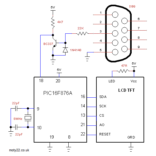
LCD TFT to display text using PIC16F876A . Included C code and circuit diagram. The LCD TFT module is a 1.8" 128 X160 pixel. The LCD is driven by SPI.
The text is sent to the TFT via the serial port. Each character is 8x12 pixels stored in the VB6 application; there is no memory enough in this pic for the data. For each character the VB transmit 12 bytes.
LCD TFT modules vary depending on the drive IC. The module in the project has the driver ST7735 . I bought this module directly from China because the price was more sensible.
Code was written on MPLAB and compiled with the free HI TECH C compiler V9.80
Software includes PIC code. You are free to use the circuit diagram and the software with no
limitations.
Circuit Description
See also Technical Tips
The crystal is a 8MHz.
Supply is 5V +/-10%. Input signal is TTL levels.
BC337 inverts the signal from the serial port and converts it to TTL level as needed by the pic.
The module in the project has the driver ST7735.
SERIAL PORT
DRIVING LCD
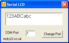
The serial port drives and powers an LCD module of 16X2 characters. Included a VB6 software, PIC C code and
a circuit diagram. The VB application transmit only the last input byte to avoid overflow of the receive register of the PIC16F628A.
The serial port can source about 4 mA which is enough to drive the pic and the LCD module. The serial port can't power LCD with LED back light.
You can read more about serial interface in http://www.beyondlogic.org/spp/serial.htm
VB6 code, PIC code and circuit diagram download (20KB). You are free to use the circuit diagram and the VB software with no limitations.
Circuit Description
See also Technical Tips
Pin 4 at the serial port is
turned to +12V by the software enabling RTS.
It is regulated to
5V by 78L05. The 5V is the supply to the microcontroller.
Pin 3 is used to drive RX input, BC337 reverse the signal phase.
LCD display and driver has 14 way connector, 10 connections are used, 4 bits data bus is selected.
There is a big selection of LCD modules, and they are very similar in characteristics i.e. DM1601, ACM1601.
Vss - Supply GRD.
Vdd - Supply 5V
Vo - Contrast Adjust
RS - Register Select
R/W - Data Read/Write
E - Enable
D4-D7 - Data Bus Lines
LCD module is 20K pot is the LCD contrast, make sure it is set.
ANALOGUE
INTERFACE TO SERIAL PORT
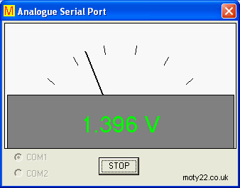
This
project is for connecting analogue signal to serial port. Included a VB6
software, PIC assembly, C code and a circuit diagram. The PIC12F675
micro controller is programmed to convert the analogue input to 10 bit
digital and transmit it in UART protocol to the serial port. The microcontroller
is powered by the signals of the serial port, so no external power
supply is needed.
You can read more about serial interface in http://www.beyondlogic.org/spp/serial.htm
Software includes PIC code and VB6 code (20KB). You are free to use the circuit diagram and the software with no
limitations.
Circuit Description
See also Technical Tips
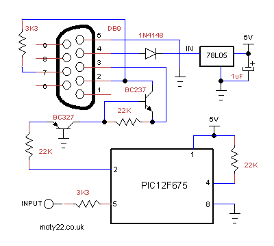
Pin 4 at the serial port is
turned to +12V by the software enabling RTS. It is regulated to
5V by 78L05.
The 5V is also the reference voltage.
Pin 3 is at -12V and pin 7 at +12V constantly and they are used
to drive RX input between -9V (input HIGH) and +8v (input LOW) .
These levels are sufficient to drive the RS232 input.
Pin 4 at PIC12F675 is reset and pin 2 is output. The other pins
are not in use but must be left open circuit. |
![]()
moty22.co.uk 2008-2024