For signal lower than 5V use high speed comperator: eBay
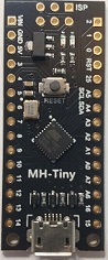
OLED FREQUENCY COUNTER ATTINY88
Counter uses low cost Nano with ATtiny88. OLED 0.96'' 128x64 or OLED 0.91'' 128x32 pixel driven by I2C interface and using
SSD1306 driver IC. ATtiny drives the Oled using software I2C.
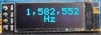
The frequency is displayed by 7 digits with leading zeros removed down to 3 digits. Signal input is a TTL type. The
timebase of 1 second is generated by the 16MHz crystal oscillator using Timer1. Timer0 is the counter.The counting resolution is 1 Hz for frequencies up to 6 MHz.
ATttiny can be programmed using Arduino IDE. Use these instructions https://handsontec.com/
OLED ACCURATE FREQUENCY COUNTER ATTINY85 RTC
ATtiny85/45 counter uses 2 PPM crystal oscillator in Real Time Clock module. The ATtiny sets the DS3231 module to output SQW 1 Hz which is used to gate the input frequency, I use this module because it is cheaper than other 2 PPM crystal oscillators. The 3V battery isn't needed.. OLED 0.96'' 128x64 or OLED 0.91'' 128x32 pixel driven by I2C interface and using
SSD1306 driver IC. ATtiny drives the Oled using software I2C. The counting resolution is 1 Hz for frequencies up to 6 MHz.
The frequency is displayed by 7 digits with leading zeros removed down to 3 digits. Signal input is a TTL type. ATtiny85 or ATtiny 45 can be used.
ATtiny can be programmed using Arduino IDE and Arduino as ISP, see Technical Tips Burning bootloader with setting "Clock Source 16MHz (PLL)", this makes the CPU work at internal 16MHz frequency.
OLED FREQUENCY COUNTER ATTINY85
Counter uses ATtiny85/45, included .ino file and circuit diagram. OLED 0.96'' 128x64 or OLED 0.91'' 128x32 pixel driven by I2C interface and using
SSD1306 driver IC. ATtiny drives the Oled using software I2C.
ATtiny can be programmed using Arduino IDE and Arduino as ISP, see Technical Tips Burning bootloader with setting "Clock Source 16MHz external", this makes the CPU work at the crystal frequency.
The frequency is displayed by 7 digits with leading zeros removed down to 3 digits. Signal input is a TTL type. The
time base is generated by the 16MHz crystal oscillator.
The counting resolution is 1 Hz for frequencies up to 6 MHz.

OLED 16MHz FREQUENCY COUNTER PIC12F629
Counter uses PIC12F629 . HEX file is included. OLED 0.96'' 128x64 or OLED 0.91'' 128x32 pixel driven by I2C interface and using
SSD1306 driver IC. Pic drives the Oled using software I2C. HEX files for both size OLED are included.
The frequency is displayed by 8 digits with leading zeros removed down to 3 digits. Signal input is a TTL type. The
time base is generated by the 32768Hz crystal oscillator. The CPU frequency is 4MHz from the internal oscillator.
The counting resolution is 2 Hz for frequencies up to 1 MHz, over 1MHz the TIMER0 prescaler is changed to 0:18 and the resolution is 16Hz.
The free XC8 compiler uses 99% of the program flash memory, using a compiler other than free XC8 ver1.45 may take less than 99% or fail for not enought memory.
OLED 128x64 from
ebay: https://www.ebay.co.uk/itm/0-96
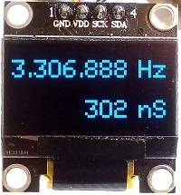
OLED SSD1331 FREQUENCY COUNTER PIC16F628A
Counter uses PIC16F628A . Included C code and circuit diagram. Color Oled display 0.95", 96 x 64, SSD1331 driver. Pic drives the Oled using software SPI.
The frequency is displayed on line 1 by 7 digits with leading zeros removed down to 1 digits. Signal input is a TTL type. The
time base is generated by the 32768Hz crystal oscillator. The CPU frequency is 4MHz from the internal oscillator.
The counting resolution is 1 Hz for frequencies up to 2 MHz.
Period is displayed on line 2. The period is calculated. For frequencies greater than 1000Hz the display is ns and for less than 1000Hz the display is in us (micro sec).
OLED module: https://www.ebay.co.uk
 
OLED 16MHz FREQUENCY COUNTER PIC12F1822
The PIC12F1822 microcontroller is programmed to count the input frequency during accurate 1 second by dividing the 8 MHz crystal. The CPU runs at 32MHz from a PLL. The counter measures the frequency for 0.1sec first, if the frequency is greater than 2MHz TMR0 prescaler divides by 4 to increase the input frequency range to 16MHz with resolution of 4Hz, when the frequency is below 2MHz TMR0 is set for no prescaling and the measurement is with resolution of 1Hz. The frequency is displayed with leading zeros removed down to 3 digits. The
font used is 5x7 pixels universal font.
OLED screen is driven by software I2C. The 470R resistors are for reducing 5V to 3.3V. The
OLED module is a 0.91" 128 X 32 pixel driven by I2C interface and using
SSD1306 driver IC. The OLED display uses low power LEDs and suitable for
battery operated frequency counter. Power can be reduced farther by
reducing contrast.
OLED FREQUENCY COUNTER FOR ARDUINO
Counter using Arduino Uno or Nano. Included ino file, C file for font, keep the ino file and C file in the same folder. The
OLED module is a 0.96" 128 X 64 pixel driven by I2C interface and using
SSD1306 driver IC. The OLED display uses low power LEDs and suitable for
battery operated frequency counter. Power can be reduced farther by
reducing contrast.
The frequency is displayed with leading zeros removed down to 3 digits. The
font used is 5x7 pixels universal font. The period is calculated. When input frequency is less than 1000Hz the period is displayed in us.
The counting is over a period of 1 second
divided from the 16 MHz crystal oscillator. The max counting is 6MHz
(Atmel specs). Period of 1 sec is generated by
the 3 internal timers.
Code is mostly in C and includes setting up the timers and counter, font
5x7 and oled initializing (no library for oled needed).
Arduino modules have either 16MHz crystal with 50 ppm tolerance or 16MHz ceramic resonator with tolerance of 0.5% and temperature stability of 0.2%. The crystal is more accurate.
 OLED 16MHz FREQUENCY COUNTER FOR PIC16F628A
Counter using PIC16F628A. The
OLED module is a 0.96" 128 X 64 pixel driven by I2C interface and using
SSD1306 driver IC. The OLED display uses low power LEDs and suitable for
battery operated frequency counter. Power can be reduced farther by
reducing contrast.
PIC16F628A uses software (bit banging) I2C.
The frequency is displayed with leading zeros removed down to 3 digits. The
font used is 8x5 pixels universal font. The period is calculated. When input frequency is less than 1000Hz the period is displayed in us.
The counting is over a period of 1 second,
divided from the 16 MHz crystal oscillator. The max counting is 8 digits
(16MHz). Period of 1 sec is generated by TMR1 and CCP1.
Code is in MPLAB X v3.10 and compilers XC8 (ver1.45).
ACCURATE OLED FREQUENCY COUNTER 16MHz PIC12F1822
PIC12F1822 counter uses 2 PPM crystal oscillator in Real Time Clock. The PIC sets the DS3231 module to output accurate 1 Hz which is used to gate the input frequency, I use this module because it is cheaper than other 2 PPM crystal oscillators. The 3V battery isn't needed.
The frequency is displayed on line 1 by 8 digits with leading zeros removed down to 3 digits. Signal input is a TTL type.
Period is displayed on line 2. The period is calculated. For frequencies greater than 1000Hz the display is ns and for less than 1000Hz the display is in us (micro sec).
OLED module is I2C 0.96" SSD1306. Contrast of oled can be set in software.

OLED SSD1331 FREQUENCY COUNTER PIC16F1827
Color Oled display 0.95", 96 x 64, SSD1331 driver. Pic drives the Oled using SPI. The counting resolution is 1 Hz for frequencies up to 8 MHz. Included C code and circuit diagram.
The frequency is displayed on line 1 by 7 digits with leading zeros removed down to 1 digits. Signal input is a TTL type, 3.3V max. The
time base is generated by the 8MHz crystal oscillator. The CPU frequency is 32MHz from the PLL.
2 diodes are used to reduce 5V to 3.5V for the PIC's Vdd, it is needed because the SSD1331 inputs don't tolerate 5V.
Period is displayed on line 2. The period is calculated. For frequencies greater than 1000Hz the display is ns and for less than 1000Hz the display is in us (micro sec).
OLED module: https://www.ebay.co.uk/
You are free to use the circuit diagram and the software with no
limitations
 
OLED 16MHz FREQUENCY COUNTER PIC16F876A
Counter using PIC16F876A. The
OLED module is a 0.96" 128 X 64 pixel driven by I2C interface and using
SSD1306 driver IC. The OLED display uses low power LEDs and suitable for
battery operated frequency counter. Power can be reduced farther by
reducing contrast.
PIC16F876A drives the oled using hardware I2C. Frequency input signal is TTL
levels, 5V max.
The frequency is displayed with leading zeros removed down to 3 digits. The
font used is 8x8 pixels universal font. The period is calculated. When input frequency is less than 1000Hz the period is displayed in us.
The counting is over a period of 1 second,
divided from the 16 MHz crystal oscillator. The max counting is 8 digits
(16MHz). Period of 1 sec is generated by TMR1 and CCP1.
After programming the PIC16F876A connect pin 1 (reset) to 5V.
Code is in MPLAB X and compilers XC8 (ver1.45).

|