|
SELF POWERED ADC INTERFACE TO PARALLEL PORT see also this
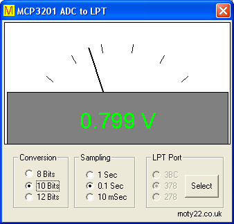
Project for connecting analogue signal to LPT printer port. Included Visual Basic 6 software and a circuit diagram. The MCP3201 is a micro-power 12 bit analogue to digital converter. The conversion selector selects the MSB when it sets to 8 Bit or 10 Bit and ignores the rest of the bits. With less resolution the reading is more stable. The supply to the circuit is via the 5V at pins that are switched to logic high by the software.
The VB6 software includes a freeware DLL from http://www.highrez.co.uk/downloads/inpout32/ ,keep the .dll file and the .exe file in the same folder.
Datasheet for the MCP3201 can be downloaded from http://ww1.microchip.com/downloads/en/DeviceDoc/21290D.pdf. LTC1285, ADS7822 are direct replacement to MCP3201.
VB6 code (30KB).

 
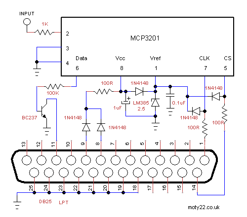
Circuit Description
See also Technical Tips
For the external supply version input is 5V.
Input at pin 2 of the ADC is 0 to 2.5 volts full range positive voltage only. The chip over voltage protection is 5V max.
Pin 8 is the supply to the IC and it is about 3.2 V.
Pin 1 is reference voltage for the ADC and cannot be changed because it regulates the supply to the IC.
Pin 6 is the serial data out of the ADC, BC237 is a TTL level drive.
Pin 7 is the clock for reading the data, 100pF is for filtering crosstalk from the cable.
Pin 5 is the Chip Select.
100R resistors and diodes on these lines are for clipping the voltage to the Vcc of the IC.
LPT plug
Pins 23,34,25 are earth. Pins 1,11,14 are inputs and outputs used for reading the ADC data. Pins 8,9 are switched to 5 V ,
output high, by the software and are used for powering the circuit.
LCD DISPLAY
INTERFACE TO PARALLEL PORT see also usb_lcd.php
A project of connecting
LCD display module to LPT printer port with multi lines and adjustable characters number. Included a VB6 software, Visual Studio 2005 VB and
a circuit diagram. There are several makes of this module that are interchangeable, the one I used is UC-16207. The LCD module has a 14 way connector, 8 pins are used for data, 2 for supply, register select(RS), read/write, enable (E) and contrast adj. The R/W input must be connected to earth to make sure that data lines are in input mode. The VB application has only basic functions, it can be changed to interface the display for a variety of inputs.
The LCD module requires a delay of 2 ms or longer for some of the commands and clock (Enable) of 10 us or longer. By loop counting during Timer1 of 100 ms interval the speed of the cpu can be assessed and used to set micro-second time base.
The io.dll file has to be in the same folder as the exe file.
You can read more about LPT interface in http://www.beyondlogic.org/spp/parallel.htm
The download includes a freeware DLL (io.dll) which can be updated from http://www.geekhideout.com/iodll.shtml
Keep the .exe file and .dll in the same folder.  
Circuit Description
See also Technical Tips
5 volt supply can be an external
power supply, using the hosting computer 5V is much preferred because
variation between the computer 5V and the external 5V can lead to
undesirable currents through the data lines. 5 volt supply is available
at a USB port or the 4 way peripherals connector from the internal
power supply unit.
Module can work with voltage range of 3.3 to 5 volts. Below 5 V the module doesn't initiate on power up so the VB extra instructions have to be enabled.
20K trimmer is needed to adjust the contrast voltage which vary with different batches of LCD.
Pins 7 to 14 of the LCD are data inputs. Pin 6 is clock input, enables LCD module to read the data.
Pin 4 is Register Select input, it is used for 16 bits instruction.
ANALOGUE
INTERFACE TO PARALLEL PORT
A project of connecting
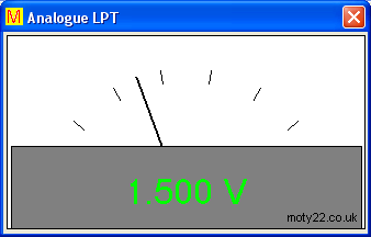
analogue signal to LPT printer port. Included a VB6 software and
a circuit diagram. The ADC0804 is an 8 bit analogue to digital converter.
74HC4052 multiplexes the 8 bits output of the ADC into 2 data lines,
it is needed because most LPT's have only 5 input lines. 74HC4052 can be replaced by 4052B CMOS.
You can read more about LPT interface in http://www.beyondlogic.org/spp/parallel.htm
The VB6 software includes a freeware DLL (inpout32.dll) from
http://www.highrez.co.uk/downloads/inpout32/
VB6 code (30KB). Keep the .exe file and .dll in the same folder. You are free to use the circuit diagram and the VB software with no
limitations.
 
Circuit Description
See also Technical Tips
5 volt supply can be an external
power supply, using the hosting computer 5V is much preferred because
variation between the computer 5V and the external 5V can lead to
undesirable currents through the data lines. 5 volt supply is available
at a USB port or the 4 way peripherals connector from the internal
power supply unit.
10k resistor and 470pF are for setting the internal clock of the
ADC.
Input at pin 6 of the ADC is 0 to 5 volts full range positive voltage
only. The chip over voltage protection is 30V max.
Pins 2 and 3 of LPT select the 2 out of 8 bits to be read. Pins
15 and 13 read the selected 2 bits. Pin 1 initiates the ADC.
74HC4052 can be replaced by 4052B CMOS 4000 series.
|
![]()
moty22.co.uk 2008-2025