The clock uses DS3231 Real Time Clock module. MODE button is for setting time and date. Hr sets the hour, mi setst minutes, Dy sets days and Yr sets year.
The DF Player plays many
sound formats. The talking clock can be used in other languages. In
languages that numbers are read in different order, like Arabic, section of
the code has to be changed and number of tracks changed too. MP3 files in
English can be downloaded above.
Display is 16x2 LCD, HD44780
compatible. Format the card with FAT32. No folders or
subfolders.
Copy to the root folder the files, one at a time and in this order; 0 to 19 (20 files),20,30,40,50,"hours","minutes","good day" (or any other message). Totally 27 files. If you make a mistake while copying the files to the
SD it isn't good enough to delete a file, you must start again with
formatting the SD. The reason for loading the files one at a time is
that if you load them together the PC sends them to the card in the
order it finds fit, and when the code plays them it picks up the files
without searching for their name.
DFPlayer mini module is sold as MP3 player. https://www.ebay.co.uk
470R resistor is to reduce the 5V output of the Arduino to 3.3V input of the DFPlayer.
Connecting 10-100
ohm resistor in series to the speaker reduces the current from the 5V
supply.
LCD TALKING REAL-TIME-CLOCK PIC16F876A
The clock uses DS3231 Real Time Clock module. MODE button is for setting time and date. Hr sets the hour, mi setst minutes, Dy sets days and Yr sets year.
The DF Player plays many
sound formats. The talking clock can be used in other languages. In
languages that numbers are read in different order, like Arabic, section of
the code has to be changed and number of tracks changed too. MP3 files in
English can be downloaded above.
Display is 16x2 LCD, HD44780
compatible. Format the card with FAT32. No folders or
subfolders.
Copy to the root folder the files, one at a time and in this order; 0 to 19 (20 files),20,30,40,50,"hours","minutes","good day" (or any other message). Totally 27 files. If you make a mistake while copying the files to the
SD it isn't good enough to delete a file, you must start again with
formatting the SD. The reason for loading the files one at a time is
that if you load them together the PC sends them to the card in the
order it finds fit, and when the code plays them it picks up the files
without searching for their name.
DFPlayer mini module is sold as MP3 player. https://www.ebay.co.uk
470R resistor is to reduce the 5V output of the Arduino to 3.3V input of the DFPlayer.
Connecting 10-100
ohm resistor in series to the speaker reduces the current from the 5V
supply.
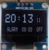
ARDUINO OLED TALKING ALARM-CLOCK
The clock uses ATMEGA328 internal timers
to get 1 second time base which is as accurate as the 16MHz crystal. The
code works for Arduino Nano and Uno only.
The DF Player plays many
sound formats. The talking clock can be used in other languages. In
languages that numbers are read in different order, like Arabic, section of
the code has to be changed and number of tracks changed too. MP3 files in
English can be downloaded above. Track 28 (alarm sound) can be replaced by a song you like.
MODE button is for setting time and volume. M_C sets the clock, M-A setst alarm time, M-O sets alarm ON/OFF and M-V sets volume.
When power comes on after power cut TALK button has to be presset to start the clock.
Display is OLED 0.96", SSD1306, I2C.
DF Player is a mini MP3 player from Ebay. Format the card with FAT32. No folders or
subfolders.
Copy to the root folder the files, one at a time and in this order; 0 to 19 (20 files),20,30,40,50,"hours","minutes","good day" (or any other message), alarm. Totally 28 files. If you make a mistake while copying the files to the
SD it isn't good enough to delete a file, you must start again with
formatting the SD. The reason for loading the files one at a time is
that if you load them together the PC sends them to the card in the
order it finds fit, and when the code plays them it picks up the files
without searching for their name. The software includes wave files in
English.
DFPlayer mini module is sold as MP3 player for Arduino. https://www.ebay.co.uk
1K resistor is to reduce the 5V output of the Arduino to 3.3V input of the DFPlayer.
OLED display is SSD1306 can be bought from Ebay.
Connecting 10-100
ohm resistor in series to the speaker reduces the current from the 5V
supply.
ARDUINO LCD AND SD CARD TALKING CLOCK
The clock tells the time by playing back
tracks from the SD. The SD (2-32GB) is FAT32 formatted. The tracks are wave
(.wav) files of 22.050 KHz, 8 bits, mono. SD card interface is in
SPI mode. The clock has an hourly announcement of time. The optional NIGHT SWITCH when closed disables the
hourly announcement.
The LCD module is 2 lines 16 characters.
The ATMEGA328P generates audio using PWM.
Sound tracks can be any sound. The code doesn't read the file name, it goes to the file number in the list of 27 files. The code plays tracks
in this order: tens of hours, hours, "hours", tens of minutes, minutes,
"minutes" and then a message, for example; "have a nice day".
Good free specifications for SD can be found in SanDisk PDF: http://alumni.cs.ucr.edu/~amitra/sdcard/ProdManualSDCardv1.9.pdf The SD
card has to be prepared this way:
Files have to be
22.050 KHz, 8 bits, mono. With short names
(max 8 characters).
Format the card with FAT32. No folders or
subfolders.
Copy to the root folder the files, one at a time and in this order; 0 to 19 (20 files),20,30,40,50,"hours","minutes","good day" (or any other message). Totally 27 files. If you make a mistake while copying the files to the
SD it isn't good enough to delete a file, you must start again with
formatting the SD. The reason for loading the files one at a time is
that if you load them together the PC sends them to the card in the
order it finds fit, and when the code plays them it picks up the files
without searching for their name. The software includes wave files in
English.
LCD supply is 5V. The SD Card supply is only 3.3V (3-3.6V) The 3.3V
and 5V are generated on the Arduino board.
The PWM output is boosted by 2 transistors push-pull. The signal to
the speaker is PWM of 62 KHz and the speaker outputs the modulated audio
only. The speaker should be 8 ohms or higher.
Digital outputs from the Arduino to the SD card use 1K and 2K resistors to reduce the 5V signals to 3.3V. SD output at pin 7 is 3.3V but is enough to drive the input.
The pins number are for ordinary SD card, for MicroSD the pins are
different.
Link between Arduino pins 3 and 5 connect 1000 Hz clock
from timer 2 to timer 1, these timers generate 1 minute time base.
LCD display and driver has 14 way connector, 10 connections are used, 4
bits data bus is selected. 10K pot adjusts the contrast. Use 16 x 2 LCD
module.
PIC16F628A LED MODULE TM1637 TALKING CLOCK
Time base is set by dividing 4MHz crystal using CCP1and TMR1. LED module is 9mm 4 digits of 7 segment.
Pressing TALK requests relevant
tracks of hours and minutes to be played. Tracks can be changed to any
language, wav or mp3, you can also record your own voice.
The SD card in the player must be
formatted to FAT32. The player reads the tracks in the order they are
written (not by the names), as an example track 53msg.mp3 is read by the
dfplayer . Tracks files must be copied to the SD one
track at a time and in the order they are in the computer folder. No
other files or folders should be on the card. If you
wish to change any of the tracks you need to reformate the SD first and
then copy the new files.
Datasheet for the DFPlayer: http://www.picaxe.com/docs/spe033.pdf
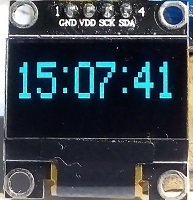
PIC16F628A OLED TALKING CLOCK
OLED: The pic drives the OLED using software I2C (bit banging). Time base is set by dividing 4MHz crystal using CCP1and TMR1. OLED module is 0.96", I2C, SSD1306 driver, 128x64.
Pressing TALK requests relevant
tracks of hours and minutes to be played. Tracks can be changed to any
language, wav or mp3, you can also record your own voice.
The SD card in the player must be
formatted to FAT32. The player reads the tracks in the order they are
written (not by the names), as an example track 53msg.mp3 is read by the
dfplayer . Tracks files must be copied to the SD one
track at a time and in the order they are in the computer folder. No
other files or folders should be on the card. If you
wish to change any of the tracks you need to reformate the SD first and
then copy the new files.
Datasheet for the DFPlayer: http://www.picaxe.com/docs/spe033.pdf
PIC LCD DFPlayer TALKING CLOCK
The pic drives the LCD to display hours
and minutes. Time base is set by dividing the crystal oscillator. Using PIC16F876A/628A.
Pressing TALK requests relevant
tracks of hours and minutes to be played. Tracks can be changed to any
language, wav or mp3, you can also record your own voice.
The SD card in the player must be
formatted to FAT32. The player reads the tracks in the order they are
written (not by the names). Track files must be copied to the SD one
track at a time and in the order they are in the computer folder. No
other files or folders should be on the card. If you
wish to change any of the tracks you need to reformate the SD first and
then copy the new files.
Datasheet for the DFPlayer:
http://www.picaxe.com/docs/spe033.pdf The LCD module is HD44780
compatible, most modules on sale are. It can be 1 or 2 lines.
You are free to use the circuit diagram and software with no
limitations.
DFPlayer mini module is sold as MP3 player for Arduino. https://www.ebay.co.uk
1K /470R resistor is to reduce the 5V output of the PIC to 3.3V input of the
DFPlayer.
Volume can be controlled by pushbuttons connected to pins
9, 11 of the DFPlayer, see the datasheet.
Connecting 10-100 ohm resistor in series to the speaker reduces the volume and the
current from the 5V supply.
LCD display is 1 or 2 lines 16 characters module.
Pic16f876a link
between pins 11 and 12 connects output of CCP2 to the input of TIMER1.
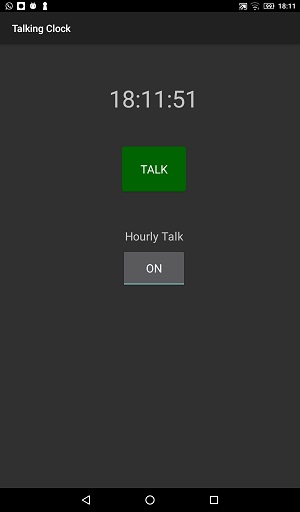
ANDROID TALKING CLOCK
The clock uses Text To Speech built in Android device, for reading the
time. It reads time hourly at the background. The app is made in B4A
(basic for Android).
Included code for the app, if you wish to change it download free IDE from:
https://www.b4x.com/
To install the app on Android device place the APK file in the device,
when you open the file it ask if you want it installed. Leave the
clock running in your office so at least once every hour you get to hear
something that makes sense.
30.12.2022 - 05:06 Name: Moty Comment: What microcontroller are you using? Do you have the part number of your LCD display?
30.12.2022 - 04:37 Name: Prantik Comment: hey,I have completed this circuit on PCB, display also works but not showing time . we have also set the potentiometer and it still not working. help me out ?
05.09.2022 - 17:20 Name: Moty Comment: Hi Bob, Dowload of this project is together with the next project on the page. There is a line in the code that disables hourly talk when you comment it. Have fun coding.
05.09.2022 - 09:14 Name: Bob Comment: Hi Moty, Nice projects - I cannot find where to download the software for your first listed talking clock using Arduino, SSD1306 and DFPlayer. Secondly someone called Sadk, asked about "Time on demand, by depressing a button" have you done a software version of this? Am using Arduino IDE ver 2.0 to edit text. Look forward to your response, please.
20.06.2022 - 12:48 Name: Moty Comment: The connections in the drawing are for SD card, for microSD card use an adapter.
Format the SD card befor uploading the wav files you downloaded.
20.06.2022 - 10:07 Name: ashok Comment: ARDUINO LCD AND SD CARD TALKING CLOCK - showing SD Error kindly help me
03.05.2022 - 02:58 Name: Sadk Comment: Using ((b4a)) application, how can only output sound when I press talk to (((arduino)))
01.05.2022 - 12:07 Name: Moty
Comment: Edited: Hi Sadk,
If you are using the b4a IDE then in module "Starter" line 18 change 'timer1.Enabled=True' to 'timer1.Enabled=False'. In module "main" remove line 50 (Starter.timer1.Enabled=True).
If you don't use the IDE let me know and I will publish another version for you.
01.05.2022 - 02:04 Name: Sadk Comment: Using ((b4a)) application, how can only output sound when I press talk to (((arduino)))
05.08.2020 - 19:25 Name: Alex Comment: Hello Moty! I found a gigrostat and I'm taking my question off.
27.07.2020 - 19:23 Name: Alex Comment: Hello Moth! The clock never went, I took it apart. Can you make a gigrostat (a device for controlling humidity within certain limits by controlling the air humidifier) on ARDUINO, DHT11 (22), a four-bit seven-segment LED indicator with a common cathode?
26.07.2020 - 21:32 Name: Moty Comment: Format the SD again and load the files with no folder.
26.07.2020 - 11:37 Name: Alex Comment: Hello Moth! The clock doesn't work as it should. After powering the buttons, time is set, but after pressing the talk button, time sounds, and then all the sound files sound completely, then time stops, and there is no reaction to the buttons. If you press the conversation button immediately after the power supply, the time is not set by the buttons. I use a 4 gigabyte micro SD card with microSD card adapter according to your scheme.
09.03.2020 - 18:11 Name: Alex Comment: Copy audio files to a folder on an SD Card or simply to a card?
08.03.2020 - 17:19 Name: Alex Comment: Hi Moty! Why do all sound files sound after speaking time?
08.03.2020 - 13:26 Name: Moty Comment: The sound being an hour ahead is because the SD isn't set properly. Try another SD card, preferably 1 to 8 GB.
07.03.2020 - 17:13 Name: Alex Comment: Hi Moty! I have a photodetector, but I thought it was just for talking_clock_hourly firmware. Formatting FAT32, copied the .wav files one at a time, starting from scratch as written. After switching on, the LED L on the Arduino Nano board does not light, but after pressing the Talk button, the time sounds (by the way, an hour ahead) then all the sound files, the LED L lights up and then lights constantly. And there 's no reaction to pressing buttons.
07.03.2020 - 16:17 Name: Moty Comment: Hi Alex,
Your wiring is most likely ok otherwise you wouldn't hear a sound.
If you don't have the photo sensor connect pin 4 of the Arduino to ground.
Use SD or SDHC card only. Format it FAT32 and copy the wav files one at a time starting from zero as described in this page.
07.03.2020 - 13:33 Name: Alex Comment: I apologize - Moty
07.03.2020 - 13:30 Name: Alex Comment: Hi Moth! It 's the same (firmware talking_clock). After pressing the Talk button, the time sounds and then all the sound files sound completely, then the time stops and there is no reaction to the buttons. This is the case with the speaker turned on and the speaker turned off. I use the micro SD card according to the diagram in the article (with resistors) with the corresponding outputs. All connections are checked according to the diagram.
06.03.2020 - 18:03 Name: Moty Comment: Hi Alex,
I made a mistake putting the wrong files. Please download the software and try it.
06.03.2020 - 10:59 Name: Alex Comment: Hello Moth! Turned off the speaker, connected the power supply with more power - after pressing Talk, the time sounds, and then all the sound files are completely. Then time stops and does not respond to the buttons.
03.03.2020 - 14:54 Name: Moty Comment: Hi Alex,
If the two versions of firmware don't work it looks like you have a fault with the hardware. When I get a chance I will check the hourly code.
27.02.2020 - 15:21 Name: Comment: Hi Moty! When using talking_clock_hourly firmware, it is not possible to set the time with buttons because the numbers change very quickly. No reaction to the photodetector.
27.02.2020 - 13:27 Name: Moty Comment: Hi Alex,
It could be the 5V power supply not powerful enough to drive the speaker. Try it again with the speaker disconnected.
26.02.2020 - 07:34 Name: Alex Comment: Hi Moty!
After turning on the clock (talking_clock firmware), you can set the clock and minute readings. After you click Talk, the time sounds and then all the sound files are completely. Then the time stops and there is no reaction to the buttons.
20.01.2020 - 17:44 Name: Alex Comment: Hi, Moty! It's cool! Many thanks!!!
Which program created sound files?
20.01.2020 - 15:42 Name: Moty Comment: Hi Alex, You can download the revised software.
19.01.2020 - 17:42 Name: Alex Comment: Hi, Moty! I can make a mistake with the line number. Write between which lines it is necessary to insert.
I had such a photo sensor in mind.
https://aliexpress.ru/item/32944049713.html?spm=a2g0o.productlist.0.0.1dc012e3CchuDz&algo_pvid=8824da4e-8f87-4c8a-957a-caf08962056d&algo_expid=8824da4e-8f87-4c8a-957a-caf08962056d-4&btsid=e15cbbc7-58c3-4310-96f2-0c16950a0914&ws_ab_test=searchweb0_0,searchweb201602_7,searchweb201603_53
19.01.2020 - 15:32 Name: Moty Comment: Hi Alex, Add this if(digitalRead(4)){Htalk=0;} at the top of loop function (line 80). During night pin 4 is connected to 5V.
18.01.2020 - 18:28 Name: Alex Comment: Hi, Moty! Many thanks!!!
Still request. Change the code so that the clock does not talk at night by disconnecting from the photo sensor (digital photo sensor for ARDUINO with Aliexpress).
18.01.2020 - 13:46 Name: Moty Comment: Hi Alex, I've added the code of hourly talk to the downloaded software.
17.01.2020 - 10:16 Name: Alex Comment: Hi, Moty!
Please write the changed lines of code. It is very necessary!
16.01.2020 - 15:48 Name: Moty Comment: To make the clock talk every hour it needs one or two lines of the code changed.
15.01.2020 - 18:40 Name: Alex Comment: Hi!
Hours on ARDUINO can play time every hour? If not, can it be done?
02.01.2020 - 13:44 Name: Moty Comment: Hi Alex,
It takes 20KB per second so it's 72MB for an hour recording.
02.01.2020 - 10:42 Name: Alex Comment: Hi!
What capacity should the SD card be for speaking hours on Arduino?
16.12.2019 - 12:41 Name: Moty Comment: Hi Alex, You don't need to connect external clock. Timer 2 divides the crystal 16 MHz to 1000 Hz. The output of timer 2 at pin 3 drives the input of timer 1 at pin 5. Timer 1 divides 1000 Hz by 60,000 to 1 minute.
16.12.2019 - 10:16 Name: Alex Comment: ARDUINO
"Link between Arduino pins 3 and 5 connect 1000 Hz clock from timer 2 to timer 1, these timers generate 1 minute time base."
Explain it in more detail. Need to connect an external clock?
06.05.2019 - 22:36 Name: Moty Comment: Sorry I was misleading you with the term RS232, the pic and the player communicate serially at TTL levels so their UART are connected directly' no max232 needed.
http://www.picaxe.com/docs/spe033.pdf
http://www.picbasic.co.uk/forum/attachment.php?s=4d33b151492596d92735014e4094ffd7&attachmentid=8726&d=1530090274
Are the datasheet, you can google for more docs.
https://github.com/Indo-Ware/dfplayer-mini-mp3 is a sample for interfacing arduino, it will be similar with pic. To play a track (0 to 2999) you send a command of 9 bytes. I've never written a code for the player. I may find some free time to try some code, I have a pic16f876a and a DFplayer.
My project has a disadvantage, when the cpu plays the SD it can't run the clock, so it can't display seconds. With the player or the TTS this can be overcome.
Please send me a link to the source of the TTS module, maybe I can buy one to play with (if it's up to $10). It needs assessing how much memory is needed to store all the words in the pic.
06.05.2019 - 17:18 Name: coding4fun Comment: I forgot to add my name on the last post. Anyways, I imagine if you have to use RS232, then you must connect a MAX232 via the pic16f876a to the Dfplayer module. am i on the right track? idk, since I don't have a sample dfplayer module in my hand yet. do you have a link to the datasheet??
06.05.2019 - 17:10 Name: Comment: Thank you for the great input. If you want to work on TTS with me then leave me your email address and I will send you a TTS module and PIC16F876A for FREE. I'm working on interfacing the module by UART, since the manual is in Chinese I am having trouble. You can join this project with me if you like. In regards to the "DFPlay" THANK YOU. Do you have any PIC16F876A sample code and schematic using this successfully, if so I would love to try it.
I've been following your work and I would love to see the new code for PIC16F876A for this project. Keep up the good work!
Thank you.
05.05.2019 - 19:41 Name: Moty Comment: I have on my list to modify the pic project to work like the arduino. the pic's PWM isn't very clever and it gives reduced sound quality in compare to the arduino. Some new pic include DAC that will give better sound. The interference between the crystals is also a problem.
Your idea to add a TTS module (text to sound) is a good one but the cost of existing TTS is high. Another option is to use MP3 player that has SD card and you call a track using RS232. https://www.ebay.co.uk/itm/TF-Card-U-Disk-DFPlay-Mini-MP3-Player-Audio-Voice-Module-For-Arduino-Red-Black/332191775209?hash=item4d582c39e9:m:mipJiSTcU06odSU7dsEBqGA
05.05.2019 - 18:18 Name: Comment: Oops, I was wrong. These .wav files are only for Arduino. Wow! For Pic, you actually have to record your own files. Is there any other way? Especially for those who don't want to record their files. I presume not because of the reading style. Have you ever used any text to speech modules? I would love to chat with you about those. Thanks.
05.05.2019 - 17:23 Name: coding4fun Comment: Never mind, I found the .wav files in the ARDUINO folder, I'm using a PIC16F876A so I had no interest in ARDUINO. Had I never checked I would be lost.
05.05.2019 - 17:19 Name: coding4fun Comment: Where can I download the .wav files you used to make this project? I find it hard trying to create my own. It would be easier if you could provide the same ones that you used, please. Thank you.
22.05.2018 - 23:03 Name: Moty Comment: Hi Sangatee, Click the button 'download software' add the c file to your project in MPLAB or MPLAB X and you can edit the code if you need to. You can also load the hex file directly to your pic.
22.05.2018 - 08:30 Name: sangatee david Comment: please i mean the programing software
22.05.2018 - 08:28 Name: sangatee david Comment: how can i get the peogramming software
13.01.2018 - 20:16 Name: Moty Comment: Hi Konstantyn, These clocks tell the time only when you press the button. It is easy to add to the code to talk when the hour changes. To add alarm is a big change. The Arduino clock gives better sound.
13.01.2018 - 19:02 Name: Konstantyn545 Comment:
Is there an alarm clock here?
13.01.2018 - 19:02 Name: Konstantyn545 Comment:
Is there an alarm clock here?
13.01.2018 - 09:08 Name: Konstantyn545 Comment: Hello, I want to collect this watch, please tell me they say time every hour?
21.12.2017 - 17:19 Name: Dmitry Comment: Hi friend
please we are too soft pic16f876 , please bin file
nice day
21.12.2017 - 17:17 Name: Dmitry Comment: Hi friend
please we are too soft pic16f876 , please bin file
nice day
15.10.2017 - 22:49 Name: Moty Comment: Hi Omar, I know too little about simulators to be any help.
15.10.2017 - 19:31 Name: Omar Comment: Hi,
I simulated your clock but unfortunately, time is not moving. We will be grateful if you help us.
omarfaruksaritas@gmail.com
15.10.2017 - 15:49 Name: Moty Comment: Hi Mr Ozgur, Yes, when you set the time by pressing the buttons the internal registers (RAM) update. The LCD and the Talk read the time from those registers.
15.10.2017 - 11:56 Name: mr. özgür Comment: Greatings, I couldn't quite understand how clock states the real time. Does it set the time after i increase or decrease the numbers on lcd display?
15.10.2017 - 11:56 Name: mr. özgür Comment: Greatings, I couldn't quite understand how clock states the real time. Does it set the time after i increase or decrease the numbers on lcd display?
15.10.2017 - 11:41 Name: mr. özgür Comment: Greatings, I couldn't quite understand how clock states the real time. Does it set the time after i increase or decrease the numbers on lcd display?
02.05.2017 - 15:47 Name: Moty Comment: Hi Sangatee, Click button DOWNLOAD SOFTWARE , If it doesn't work send your email address and I'll send you the code.
02.05.2017 - 10:57 Name: Sangatee Comment: Please can I get program code
12.09.2016 - 21:51 Name: mike Comment: i find this very useful, thanx pls
19.04.2016 - 08:47 Name: dipen Comment: while simulating on proteus,clock doesnot advances
12.10.2014 - 10:33 Name: Moty
Comment: Hi Abraham. My full name is Moty Santos Jelahlibahd.
11.10.2014 - 15:32 Name: Abraham Comment: can I get your name?
I want to reference u you I my Project.
02.06.2014 - 12:08 Name: Moty Comment: Hi Yusa. 2 GB SD allows for about 20 minutes for each track. The clock doesn't advance during playing the tracks so for the clock showing the right time a track has to be limited to 2 seconds.
02.06.2014 - 02:09 Name: Yusa Comment: How many seconds can a track be.